Rockwell Automation 1391 USER MNL/DIGITAL AC SERVO DR User Manual
Page 78
Chapter 8
Start-Up
8-10
ATTENTION: If an oscilloscope (or chart recorder) is used
during Start-Up or Troubleshooting, it must be properly
grounded. The oscilloscope chassis may be at a potentially fatal
voltage if not properly grounded. Always connect the
oscilloscope chassis to earth ground.
When using an oscilloscope (or chart recorder) it is
recommended that the test probe ground be connected to TB2-5.
!
38.
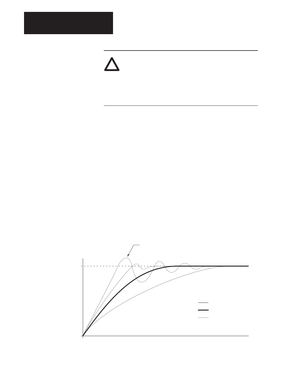
Adjust parameter 168 (Kp Velocity Loop) and observe the velocity
response (at TB2-4) profile at various levels of step input speed
commands. The “Underdamped” response curve in Figure 8.1 with a
single velocity overshoot of 20-30% on accel and decel is optimal
on a point to point positioning or velocity controlled system. The
“Critically Damped” curve is desirable on a contouring or metal
removing system.
Parameter 169 (Ki Velocity Loop) should be adjusted so that the
motor achieves the commanded speed or final position as quickly as
possible with little or no overshoot. In addition to the dynamic
response, the motor shaft should not oscillate or exhibit any erratic
motion at zero speed.
39.
Remove power with the branch circuit disconnect.
40.
Remove the local Enable switch and reconnect external wiring.
41.
Apply power and check system operation.
Figure 8.1
Velocity Response Profiles
Commanded Velocity
Z = 0.7
Z = 0.87
Z = 1.0
Z = 1.4
Time
Parameter 169 Controls Amount of Overshoot
Underdamped
Critically Damped
Overdamped