Event buffer overflow, Disturbance recorder, Triggering the recorder – Rockwell Automation 865 Differential Protection Relay User Manual
Page 94: Reading recordings
4-2 Supporting
Functions
865-UM001A-EN-P – July 2009
Event
Buffer
Overflow
The normal procedure is to poll events from the device all the time.
If this is not done, the event buffer will eventually overflow. On the
local screen this is indicated with string "OVF" after the event code.
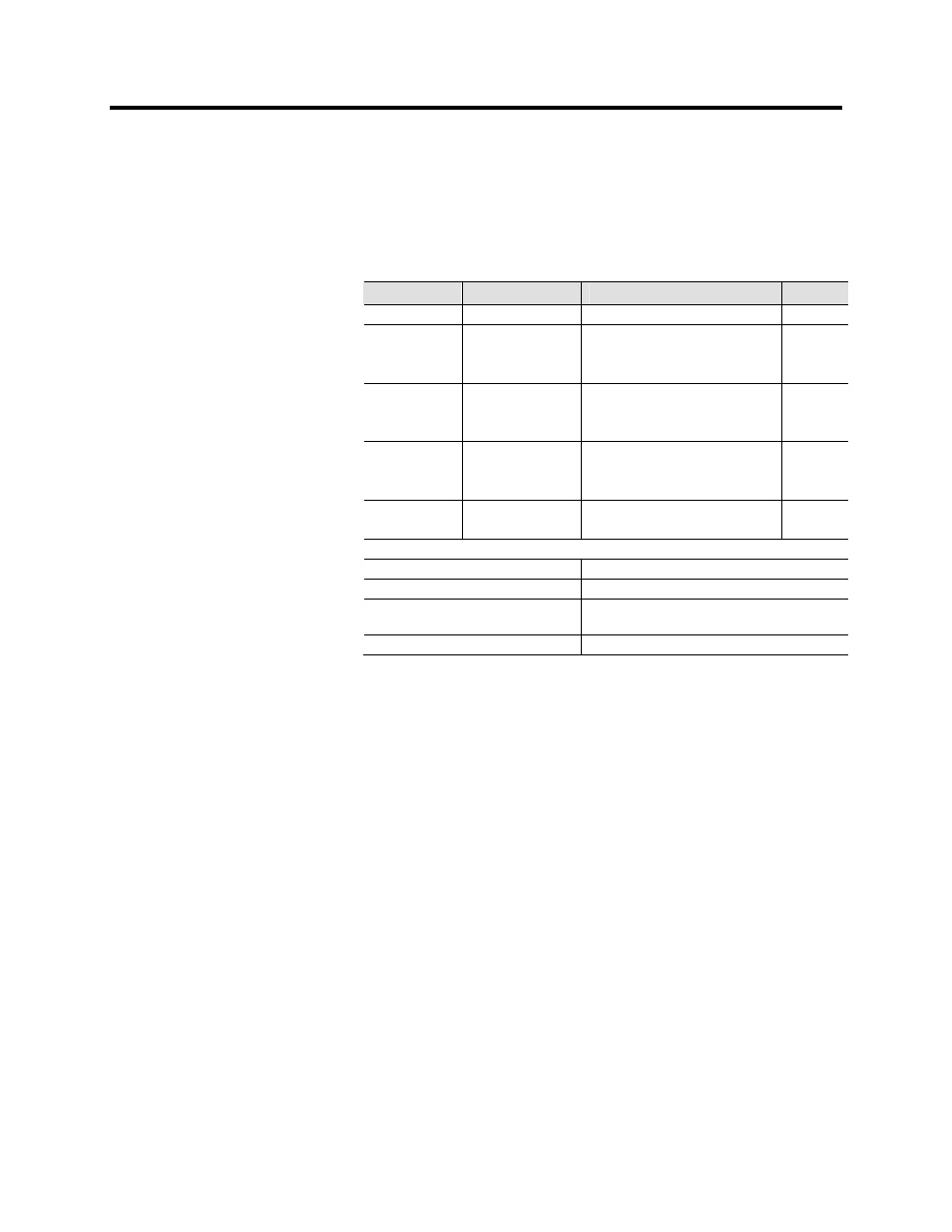
Table 4.2 – Setting Parameters for Events
Parameter
Value
Description
Note
Count
Number
of
events
ClrEn
–
Clear
Clear event buffer
Set
Order
Old-New
New-Old
Order of the event buffer for local
display
Set
FVSca
PU
Pri
Scaling of event fault value
Per unit scaling
Primary scaling
Set
Display
Alarms
On
Off
Alarm pop-up display is enabled
No alarm display
Set
FORMAT OF EVENTS ON THE LOCAL DISPLAY
Code: CHENN
CH = event channel, NN=event code
Event description
Event channel and code in plain text
yyyy-mm-dd
Date (for available date formats see “System
Clock and Synchronization” on page 4-11)
hh:mm:ss.nnn Time
Disturbance Recorder
The disturbance recorder can be used to record all the measured
signals, that is, currents, voltages and the status information of digital
inputs (DI) and digital outputs (DO). The digital inputs include also
the arc protection signals S1, S2, BI and BO, if the optional arc
protection is available.
Triggering the Recorder
The recorder can be triggered by any start or trip signal from any
protection stage or by a digital input. The triggering signal is selected
in the output matrix (vertical signal DR). The recording can also be
triggered manually. All recordings are time stamped.
Reading
Recordings
The recordings can be uploaded, viewed and analyzed with the
SetPointPS program. The recording is in COMTRADE format. This
means that also other programs can be used to view and analyze the
recordings made by the relay.
For more details, please see a separate SetPointPS manual.