Operation indicators – Rockwell Automation 865 Differential Protection Relay User Manual
Page 16
2-4
Local Panel User Interface
865-UM001A-EN-P – July 2009
4.
Keys for selecting submenus [selecting a digit in a numerical
value] (LEFT/RIGHT)
5.
Additional information key (INFO)
NOTE: The term, which is used for the buttons in this manual,
is inside the rounded brackets.
Operation
Indicators
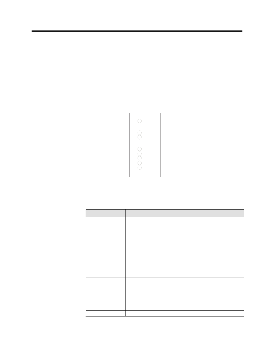
The relay is provided with eight LED indicators:
Power
Error
Com
Alarm
Trip
A
B
C
Figure 2.5 – Operation Indicators of the Relay
Table 2.1 – Operation Indicators
LED indicator
Meaning
Measure/ Remarks
Power LED lit
The power has been switched on
Normal operation state
Error LED lit
Internal fault, operates in parallel with
the self supervision output relay
The relay attempts to reboot
[REBOOT]. If the error LED
remains lit, call for maintenance.
Com LED lit or flashing
The serial bus is in use and
transferring information
Normal operation state
Alarm LED lit
One or several signals of the output
relay matrix have been assigned to
output LA and the output has been
activated by one of the signals. (For
more information about output matrix,
please see page 2-24).
The LED is switched off when the
signal that caused output Al to
activate, e.g. the START signal, is
reset. The resetting depends on the
type of configuration, connected or
latched.
Trip LED lit
One or several signals of the output
relay matrix have been assigned to
output Tr, and the output has been
activated by one of the signals. (For
more information about output relay
configuration, see “Configuring Digital
Outputs DO” on page 2-24).
The LED is switched off when the
signal that caused output Tr to
activate, e.g. the TRIP signal, is
reset. The resetting depends on the
type of configuration, connected or
latched.
A- C LED lit
Application-related status indicators.
Configurable