Ieee2 inverse time operation – Rockwell Automation 865 Differential Protection Relay User Manual
Page 85
Protection Functions
3-41
865-UM001A-EN-P – July 2009
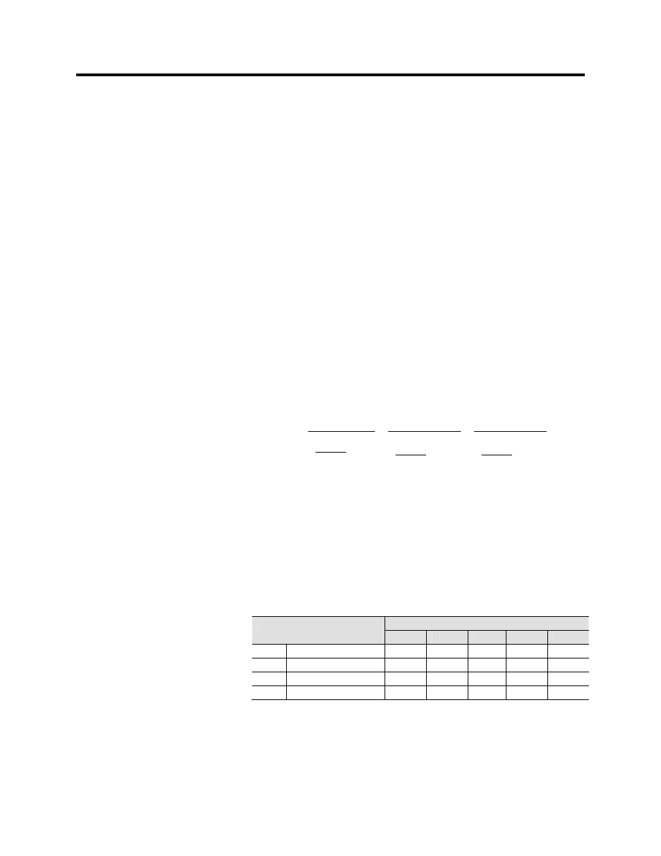
IEEE2 Inverse Time Operation
Before the year 1996 and ANSI standard C37.112, microprocessor
relays were using equations approximating the behavior of various
induction disc type relays. A quite popular approximation is
Equation 8, which in the 865 is called IEEE2. Another name could
be IAC, because the old General Electric IAC relays have been
modeled using the same equation.
There are four different delay types according Table 3.25. The old
electromechanical induction disc relays have inverse delay for both
trip and release operations. However, in the Bulletin 865 only the trip
time is inverse, the release time being constant.
The operation delay depends on the measured value and other
parameters according Equation 8. Actually this equation can only be
used to draw graphs or when the measured value I is constant during
the fault. A modified version is implemented in the relay for real
time usage.
Equation
8
⎥
⎥
⎥
⎥
⎥
⎦
⎤
⎢
⎢
⎢
⎢
⎢
⎣
⎡
⎟
⎟
⎠
⎞
⎜
⎜
⎝
⎛
−
+
⎟
⎟
⎠
⎞
⎜
⎜
⎝
⎛
−
+
⎟
⎟
⎠
⎞
⎜
⎜
⎝
⎛
−
+
=
3
2
C
I
I
E
C
I
I
D
C
I
I
B
A
k
t
pickup
pickup
pickup
t
=
Operation delay in seconds
k
=
User’s
multiplier
I
=
Measured value
I
pickup
=
User’s pick up setting
A,B,C,D
=
Constant parameter according Table 3.25
Table 3.25 – Constants for IEEE2 Inverse Delay Equation
Parameter
Delay type
A
B
C
D
E
MI Moderately
inverse
0.1735 0.6791 0.8 -0.08 0.1271
NI Normally
inverse
0.0274 2.2614 0.3 -.1899 9.1272
VI Very
inverse
0.0615 0.7989 0.34 -0.284 4.0505
EI Extremely
inverse
0.0399
0.2294 0.5 3.0094
0.7222