Chapter 10 – technical data, Connections, Measuring circuitry – Rockwell Automation 865 Differential Protection Relay User Manual
Page 171: Auxiliary voltage, Technical data, Chapter
Chapter
10
865-UM001A-EN-P – July 2009
Technical
Data
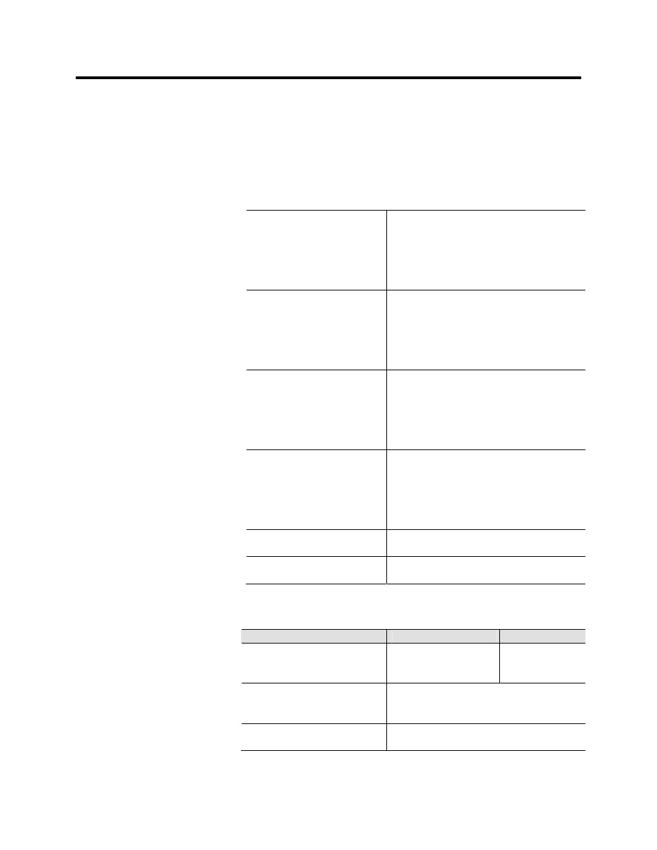
Table 10.1 – Measuring Circuitry
Rated phase current
5 A (configurable for CT secondaries 1 – 10 A)
- Current measuring range
0…250 A
- Thermal withstand
20 A (continuously)
100 A (for 10 s)
500 A (for 1 s)
- Burden
< 0.2 VA
Rated phase current
1 A (configurable for CT secondaries 1 – 10 A)
- Current measuring range
0…50 A
- Thermal withstand
20 A (continuously)
100 A (for 10 s)
500 A (for 1 s)
- Burden
< 0.1 VA
Rated residual current (optional)
5 A (configurable for CT secondaries 1 – 10 A)
- Current measuring range
0…25 A
- Thermal withstand
20 A (continuously)
100 A (for 10 s)
500 A (for 1 s)
- Burden
< 0.2 VA
Rated residual current
1 A (configurable for CT secondaries 0.1 – 10 A)
- Current measuring range
0…5 A
- Thermal withstand
4 A (continuously)
20 A (for 10 s)
100 A (for 1 s)
- Burden
< 0.1 VA
Rated frequency f
n
45 – 65 Hz
- Frequency measuring range
16 – 75 Hz
Terminal block:
Maximum wire dimension:
- Solid or stranded wire
4 mm
2
(10-12 AWG)
Table 10.2 – Auxiliary Voltage
Catalog No./ Option
Type A (standard)
Type B (option)
Rated voltage Uaux
40 - 865 V ac/dc
18...36 V dc
110/120/220/240 V ac
24 V dc
48/60/110/125/220 V dc
Power consumption
< 7 W (normal conditions)
< 15 W (output relays activated)
Max. permitted interruption time
< 50 ms (110 V dc)
Terminal Block:
Max. wire dimension:
- Phoenix MVSTBW or equivalent
2.5 mm
2
(13-14 AWG)
Connections