Output matrix, Figure 6.1 – output matrix – Rockwell Automation 865 Differential Protection Relay User Manual
Page 122
6-4 Control
Functions
865-UM001A-EN-P – July 2009
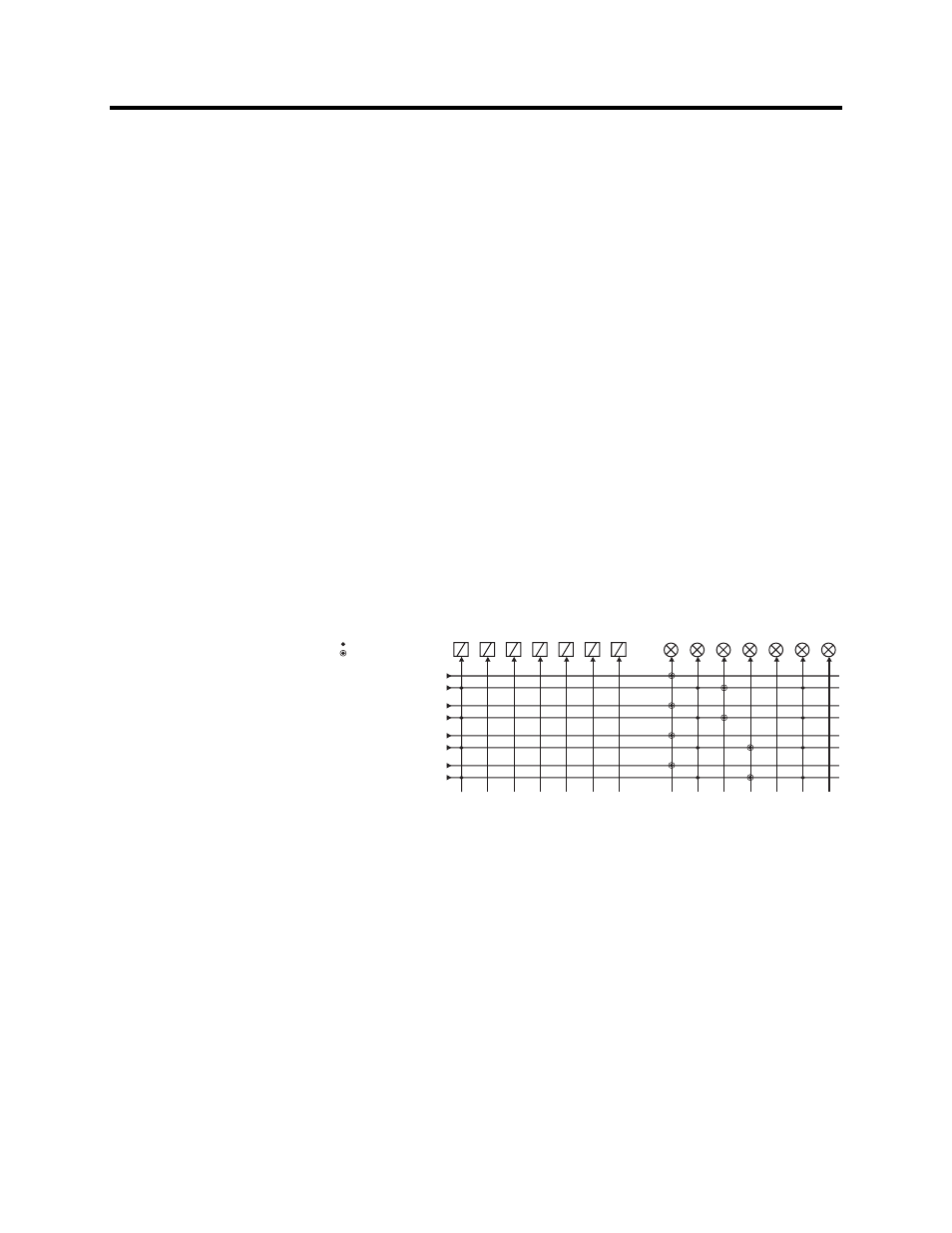
Output Matrix
By means of the output matrix, the output signals of the various
protection stages, digital inputs, logic outputs and other internal
signals can be connected to the output relays, front panel indicators,
virtual outputs etc.
There are two LED indicators named "Alarm" and "Trip" on the
front panel. Furthermore there are three general purpose LED
indicators – "A", "B" and "C" available for customer-specific
indications. In addition, the triggering of the disturbance recorder
(DR) and virtual outputs are configurable in the output matrix. See
an example in Figure 6.1.
An output relay or indicator LED can be configured as latched or
non-latched. A non-latched relay follows the controlling signal. A
latched relay remains activated although the controlling signal
releases.
There is a common "release latched" signal to release all the latched
relays. This release signal resets all the latched output relays and
indicators. The reset signal can be given via a digital input, via a
keypad or through communication. Any digital input can be used for
resetting. The selection of the input is done with the SetPointPS
software under the menu "Release output matrix latches". Under the
same menu, the "Release latches" parameter can be used for
resetting.
OUTPUT MATRIX
connected
I> start
I>> start
Io> start
Io>> start
I> trip
I>> trip
Io> trip
Io>> trip
T1
T2
A1
A2
A3
A4
A5
Alarm Trip
A
B
C
DR
VO1
connected and latched
OutputMatrix
Figure 6.1 – Output Matrix