Rockwell Automation 20-750-CNETC PowerFlex Coaxial ControlNet Option Module User Manual
Page 53
Rockwell Automation Publication 750COM-UM003B-EN-P - November 2012
53
Configuring the I/O
Chapter 4
6.
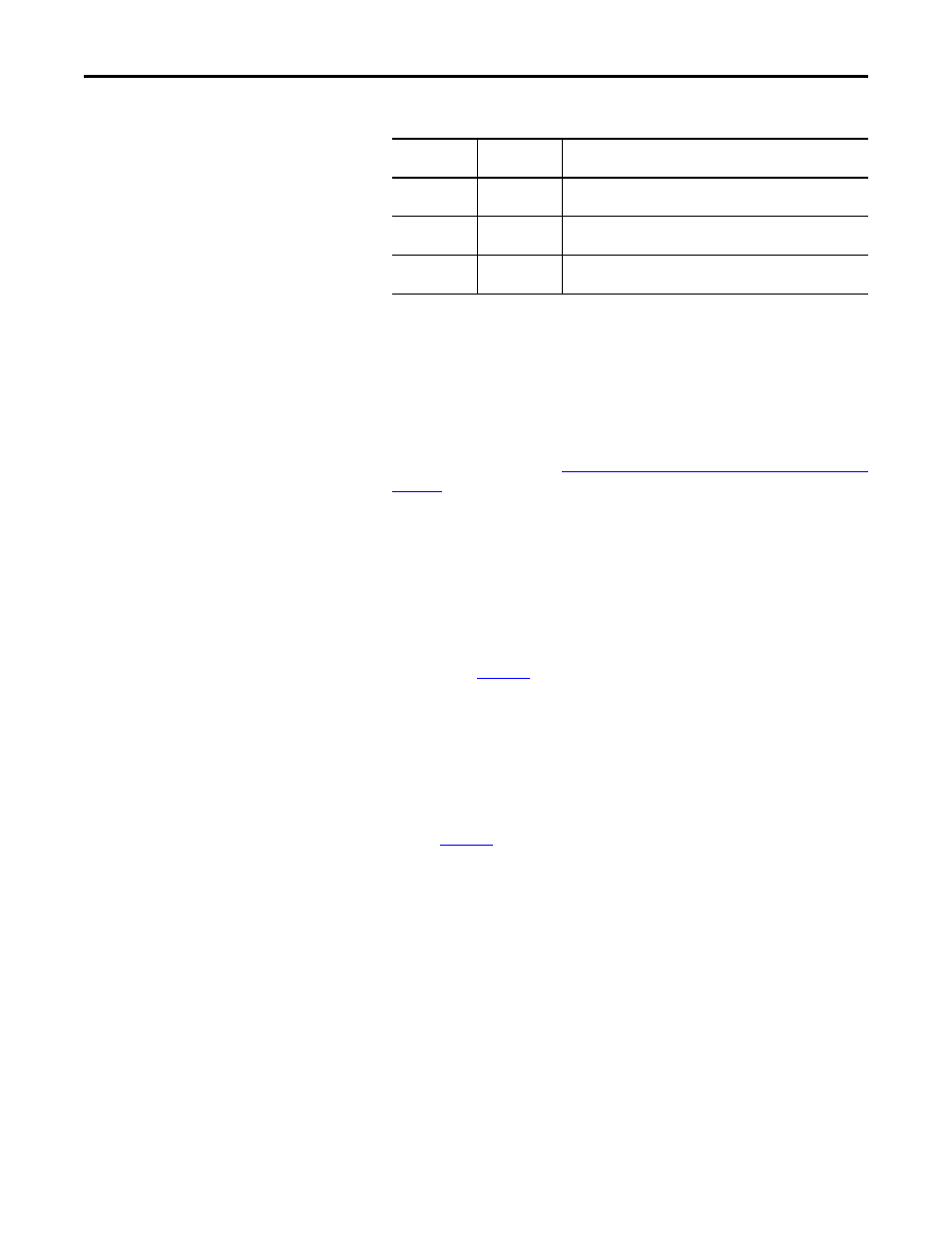
Under Connection Parameters, edit the following information.
Enter the number of 32-bit words that are required for your I/O in the
Input Size and Output Size boxes. Because the option module always uses
the 32-bit Logic Status, 32-bit Feedback, and a 32-bit word dedicated for
memory allocation of the Generic ControlNet module profile, at least
three 32-bit words must be set for the Input Size. The option module also
uses the 32-bit Logic Command and 32-bit Reference, requiring at least
two 32-bit words for the Output Size. If any or all of the drive’s sixteen 32-
bit Datalinks are used (see
Setting a Master-Slave Hierarchy (Optional) on
), the Input and Output Size settings must be increased
accordingly.
• Input Size:
Start with 3 words and add 1 word for each Datalink used
to read data. For example, if 3 Datalinks—
Host [DL To Net xx]
parameters—will be used to read drive or peripheral parameters, add 3
words to the required 3 words for a total of 6 words. You can use option
module
Device Parameter 03 - [DLs To Net Act] to check the total
number of Datalinks being used. Word 0 is a pad word, Word 1 is Logic
Status, Word 2 is Speed Feedback, Word 3 is DL To Net 01, and so
forth (see
Figure 8
).
• Output Size:
Start with 2 words and add 1 word for each Datalink
used to write data. For example, if 7 Datalinks—
Host [DL From Net
xx]
parameters—will be used to write to drive or peripheral parameters,
add 7 words to the required 2 words for a total of 9 words. You can use
option module
Device Parameter 02 - [DLs From Net Act] to check
the total number of Datalinks being used. Word 0 is Logic Command,
Word 1 is Speed Reference, Word 2 is DL From Net 01, and so forth
(see
Figure 9
).
For the example in this manual, all 16
Host [DL From Net xx] and all 16
Host [DL To Net xx] are used, resulting in an Input Size of ‘19’ and an
Output Size of ‘18’.
7.
After setting the information in the drive’s New Module dialog box, click
OK.
The Module Properties dialog box appears.
8.
Click the Connection tab.
Box
Assembly
Instance
Size
Input
1 (This value is
required.)
The value will vary based on the number of Host [DL From Net xx]
parameters used for your application (see details below).
Output
2 (This value is
required.)
The value will vary based on the number of Host [DL To Net xx]
parameters used for your application (see details below).
Configuration
6 (This value is
required.)
0 (This value is required.)