Configuring and verifying key drive parameters – Rockwell Automation 20-750-CNETC PowerFlex Coaxial ControlNet Option Module User Manual
Page 21
Rockwell Automation Publication 750COM-UM003B-EN-P - November 2012
21
Installing the Option Module
Chapter 2
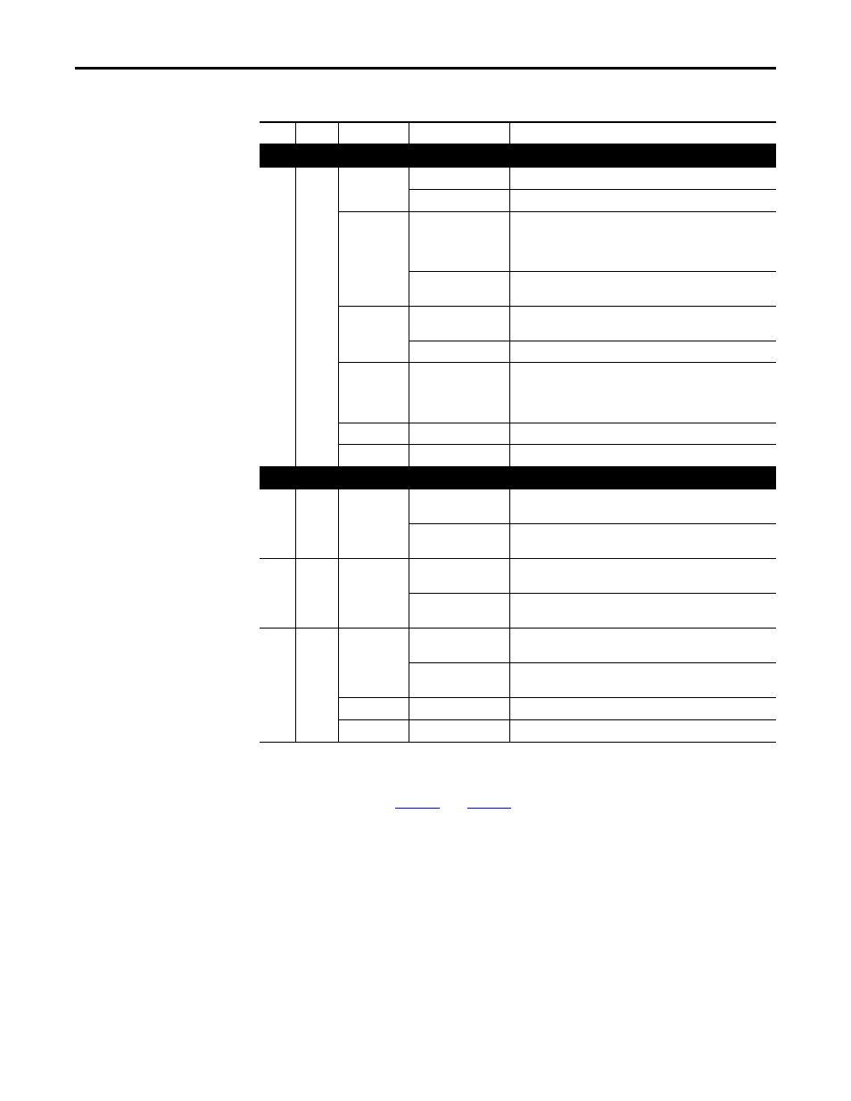
Table 1 - Drive and Option Module Start-Up Status Indications
After verifying correct operation, swing down the drive HIM bezel to its closed
position and install the drive cover. For more details on status indicator
operation, see
.
Configuring and Verifying Key Drive Parameters
The PowerFlex 750-Series drive can be separately configured for the control and
Reference functions in various combinations. For example, you could set the
drive to have its control come from a peripheral or terminal block with the
Reference coming from the network. Or you could set the drive to have its
control come from the network with the Reference coming from another
peripheral or terminal block. Or you could set the drive to have both its control
and Reference come from the network.
Item
Name
Color
State
Description
Drive STS Indicator
➊
STS
(Status)
Green
Flashing
Drive ready but not running, and no faults are present.
Steady
Drive running, no faults are present.
Yellow
Flashing
When running, a type 2 (non-configurable) alarm condition exists
– drive continues to run. When stopped, a start inhibit condition
exists and the drive cannot be started (see drive parameter 933 -
[Start Inhibits]).
Steady
A type 1 (user configurable) alarm condition exists, but the drive
continues to run.
Red
Flashing
A major fault has occurred. Drive will stop. Drive cannot be started
until fault condition is cleared.
Steady
A non-resettable fault has occurred.
Red/Yellow
Flashing Alternately
A minor fault has occurred. Use drive parameter 950 - [Minor Flt
Config] to enable. If not enabled, acts like a major fault. When
running, the drive continues to run. System is brought to a stop
under system control. The fault must be cleared to continue.
Yellow/Green
Flashing Alternately
When running, a type 1 alarm exists.
Green/Red
Flashing Alternately
Drive is firmware updating.
Option Module Status Indicators
➋
PORT
Green
Flashing
Normal operation. The option module is establishing an I/O
connection to the drive. It will turn steady green or red.
Steady
Normal operation. The option module is properly connected and
communicating with the drive.
➌
MOD
Green
Flashing
Normal operation. The option module is operating but is not
transferring I/O data to a controller.
Steady
Normal operation. The option module is operating and transferring
I/O data to a controller.
➍
➎
NET A
NET B
Green
Flashing
A temporary channel error has occurred or the channel is in ‘listen-
only’ mode.
Steady
Normal operation for that channel. The option module is properly
connected and communicating on the network.
Red
Flashing
The channel is not receiving network activity.
Green/Red
Flashing Alternately
There is an invalid link configuration for that channel.