Rockwell Automation 442L SC300 Safety Sensor User Manual User Manual
Page 34
32
Rockwell Automation Publication 10000202762 Ver 00 - January 2012
Chapter 5
Electrical installation
Principle of operation (Figure 24 and 25)
The only difference between Figure 24 and 25 are the safety relay modules are different.
The figures are both wired for the same overall functionality.
When the light path on the SC300 is clear and the input conditions on the MSR127 or
GSR SI are valid, the system is ready for switch on and waits for an input signal/switch on
signal. The system’s corresponding logic path is enabled by pressing and releasing the
related restart button. The related output on the MSR127 or GSR SI carry power. If the
input conditions are no longer met, then the related outputs on the MSR127 or GSR SI
shut down.
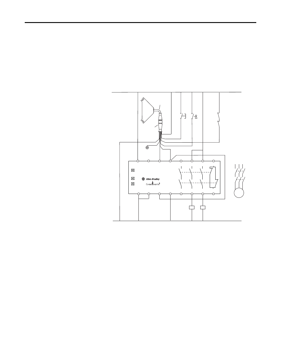
Figure 26 - SC300 safety camera configured for manual restart, EDM and external teach
connected to an MSR127TP safety relay module with automatic restart
Principle of operation
When the light path on the SC300 safety camera is clear and the input conditions on the
MSR127TP are valid, the system is ready for switch on and waits for an input signal/
switch on signal. The system’s corresponding logic path is enabled by pressing and
releasing the related restart switch. The related outputs of the MSR127TP carry power. If
the input conditions are no longer met, the related outputs of the MSR127TP open
interrupting the power.
A2
A1
S11
S21
S12
S22
S52
S34
13
14
23
24
33
41
34
42
MSR127 TP
PWR
CH1
CH2
Teach
Camera Pigtail
889D-F8AB-X
Wht
Yel
Blu
Red
Gry
Brn
Grn
Pnk
K1
K2
L1 L2 L3
M
K1
K2
Wht 1 Reset
Color Pin Signal
Brn 2 +24V
Grn 3 Teach
Yel 4 EDM
Gry 5 OSSD 1
Pnk 6 OSSD 2
Blu 7 0V DC
Red 8 FE
24V DC
0V DC
Restart
K1
K2