Connection diagrams, Msr127 – Rockwell Automation 442L SC300 Safety Sensor User Manual User Manual
Page 33
Rockwell Automation Publication 10000202762 Ver 00 - January 2012
31
Chapter 5
Electrical installation
•
If you use the internal restart interlock, then you can connect separate reset buttons or
a common reset button for both cameras.
•
If you use the external device monitoring, then must connect separate normally
closed contacts (k1, k2) for both cameras.
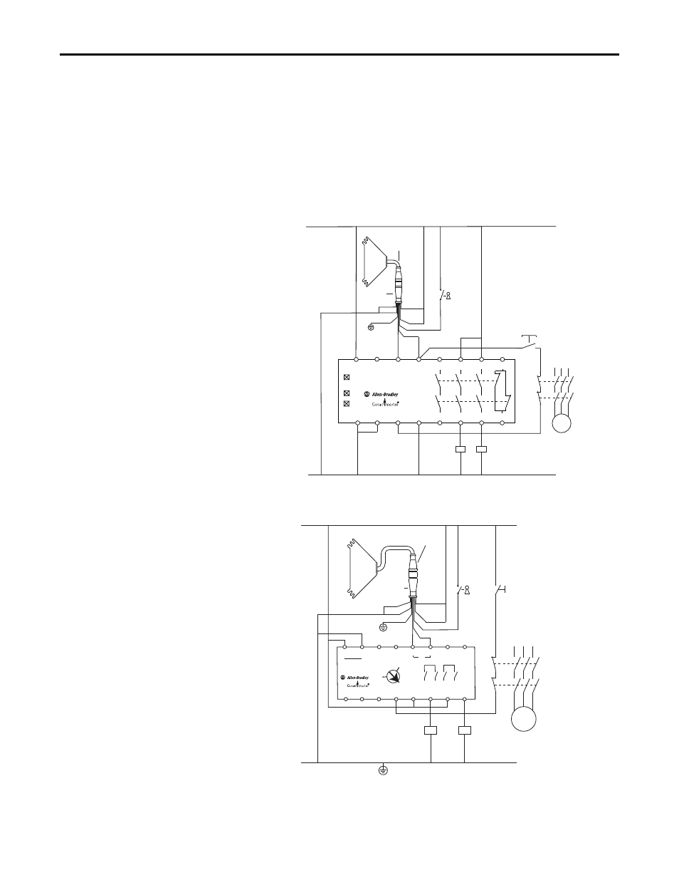
Connection diagrams
Notes
•
Take note of the related operating instructions of the integrated devices!
•
You can find more connection diagrams at www.rockwellautomation.com.
Figure 24 - SC300 safety camera configured with external teach connected to an MSR127RP wired
for monitored manual restart
Figure 25 - SC300 safety camera with external teach connected to a GSR SI safety relay module
configured for monitored manual restart
A2
A1
S11
S21
S12
S22
S52
S34
13
14
23
24
33
41
34
42
MSR127
PWR
CH1
CH2
Teach
Camera Pigtail
889D-F8AB-X
Wht
Yel
Blu
Red
Gry
Brn
Grn
Pnk
K1
K2
L1
L2
L3
M
Restart
K1
K2
Wht 1 Reset
Color Pin Signal
Brn 2 +24V
Grn 3 Teach
Yel 4 EDM
Gry 5 OSSD 1
Pnk 6 OSSD 2
Blu 7 0V DC
Red 8 FE
24V DC
0V DC
A2
A1
+
-
S11
S21
S12
S22
L12
L11
Y32
S34
13
13
14
14
23
23
24
24
24VDC
IN1
SI
RESET
0
MM
AM
Teach
K1
K2
Restart
K1
K2
L1 L2 L3
M
24V DC
0V DC
Camera Pigtail
889D-F8AX-X
Wht
Yel
Blu
Rd
Gry
Brn
Grn
Pnk
Wht 1 Reset
Color Pin Signal
Brn 2 +24V
Grn 3 Teach
Yel 4 EDM
Gry 5 OSSD 1
Pnk 6 OSSD 2
Blu 7 0V DC
Red 8 FE