Modbus datalinks in: a…d, Using datalinks with metasys n2, Using datalinks with metasys n2 -4 – Rockwell Automation 20-COMM-H RS485 HVAC Adapter FRN 2.xxx User Manual
Page 70: Orks, refer to the
7-4
Using Datalinks with All Protocols
20-COMM-H RS-485 HVAC Adapter User Manual
Publication 20COMM-UM009D-EN-P
Modbus Datalinks In: A…D
Using Datalinks with Metasys
N2
This section presents information about using Datalinks with Metasys N2
networks. For information about using Datalinks for Modbus networks or
Siemens P1 FLN networks, refer to the
and
Using Datalinks with Siemens P1 FLN
sections in this chapter.
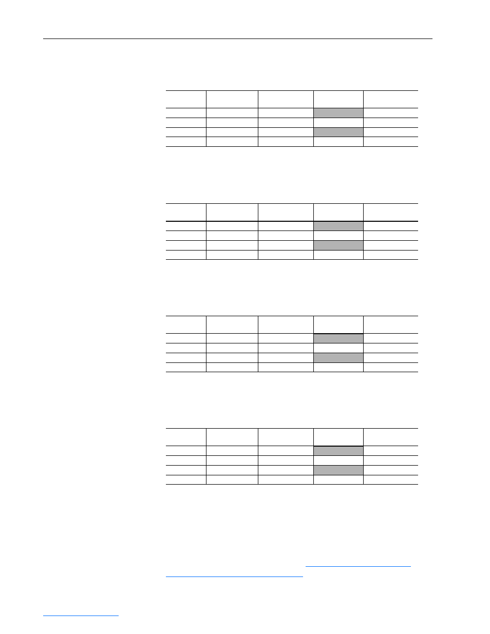
Table 7.E Modbus Datalinks In - A1, A2
Modbus
Address
Data Direction
Parameter
Description
16-Bit Datalink
32-Bit Datalink
4x0018
Register Output
Datalink A1 In
Not used
LSW of 32-bit
4x0019
(1)
(1)
A write access to address 4x0019 initiates an update of the Datalink A1 field in the DPI I/O image.
Register Output
Datalink A1 In
16-bit value
MSW of 32-bit
4x0020
Register Output
Datalink A2 In
Not used
LSW of 32-bit
4x0021
(2)
(2)
A write access to address 4x0021 initiates an update of the Datalink A2 field in the DPI I/O image.
Register Output
Datalink A2 In
16-bit value
MSW of 32-bit
Table 7.F Modbus Datalinks In - B1, B2
Modbus
Address
Data Direction
Parameter
Description
16-Bit Datalink
32-Bit Datalink
4x0022
Register Output
Datalink B1 In
Not used
LSW of 32-bit
4x0023
(1)
(1)
A write access to address 4x0023 initiates an update of the Datalink B1 field in the DPI I/O image.
Register Output
Datalink B1 In
16-bit value
MSW of 32-bit
4x0024
Register Output
Datalink B2 In
Not used
LSW of 32-bit
4x0025
(2)
(2)
A write access to address 4x0025 initiates an update of the Datalink B2 field in the DPI I/O image.
Register Output
Datalink B2 In
16-bit value
MSW of 32-bit
Table 7.G Modbus Datalinks In - C1, C2
Modbus
Address
Data Direction
Parameter
Description
16-Bit Datalink
32-Bit Datalink
4x0026
Register Output
Datalink C1 In
Not used
LSW of 32-bit
4x0027
(1)
(1)
A write access to address 4x0027 initiates an update of the Datalink C1 field in the DPI I/O image.
Register Output
Datalink C1 In
16-bit value
MSW of 32-bit
4x0028
Register Output
Datalink C2 In
Not used
LSW of 32-bit
4x0029
(2)
(2)
A write access to address 4x0029 initiates an update of the Datalink C2 field in the DPI I/O image.
Register Output
Datalink C2 In
16-bit value
MSW of 32-bit
Table 7.H Modbus Datalinks In - D1, D2
Modbus
Address
Data Direction
Parameter
Description
16-Bit Datalink
32-Bit Datalink
4x0030
Register Output
Datalink D1 In
Not used
LSW of 32-bit
4x0031
(1)
(1)
A write access to address 4x0031 initiates an update of the Datalink D1 field in the DPI I/O image.
Register Output
Datalink D1 In
16-bit value
MSW of 32-bit
4x0032
Register Output
Datalink D2 In
Not used
LSW of 32-bit
4x0033
(2)
(2)
A write access to address 4x0033 initiates an update of the Datalink D2 field in the DPI I/O image.
Register Output
Datalink D2 In
16-bit value
MSW of 32-bit