Connecting the adapter to the network, Connecting the adapter to the network -6 – Rockwell Automation 20-COMM-H RS485 HVAC Adapter FRN 2.xxx User Manual
Page 20
2-6
Installing the Adapter
20-COMM-H RS-485 HVAC Adapter User Manual
Publication 20COMM-UM009D-EN-P
Connecting the Adapter to
the Network
1. Remove power from the network and drive.
2. Use static control precautions.
3. Connect an RS-485 cable to the network, and route it through the
bottom of the PowerFlex drive (
).
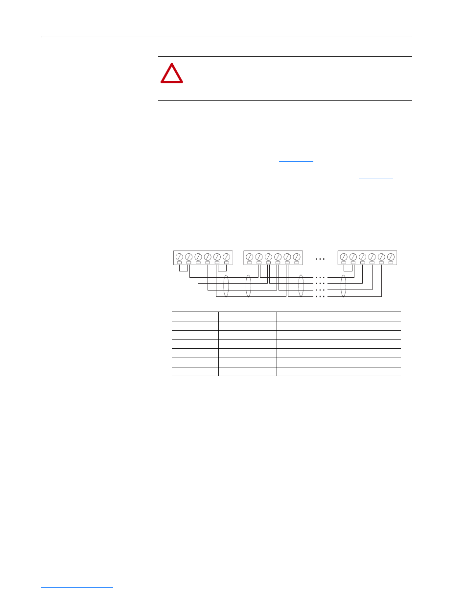
4. Connect a six-pin linear plug to the RS-485 cable. (See
Figure 2.5
for
the terminal definitions.)
Figure 2.5
Typical Network Connections
!
ATTENTION: Risk of injury or death exists. The PowerFlex
drive may contain high voltages that can cause injury or death.
Remove power from the drive, and then verify power has been
discharged before installing or removing the adapter.
Terminal
Signal
Function
TERM
Termination
(1)
(1)
Jumper terminals TERM and A on the adapter at end of the RS-485 network. This enables a built-in
RC termination network on the adapter.
Signal RC Termination
A
Signal A
TxRxD-
B
Signal B
TxRxD+
COM
Common
Signal Common
SHIELD
Shield
Shield RC Termination
GND
Ground
(2)
(2)
The shield must be grounded at a single point on the network (jumper terminals SHIELD and GND).
A 3-wire network using Belden 3106A cable or equivalent is recommended for Modbus RTU applications
and shown in Figure 2.3 above. A 2-wire network using Belden 3105A cable or equivalent (COM
terminal is not connected) can also be used for most applications. However, a 3-wire network is more
robust in noisy environments.
For Metasys N2 or Siemens P1 FLN applications, refer to published guidelines from Johnson Controls or
Siemens Building Technologies respectively.
Shield GND Termination
Node 1
Node 2
Node "n"
TERMA
B
COM SHIELD
GND
TERMA
B
COM SHIELD
GND
TERMA
B
COM SHIELD
GND