Rockwell Automation 20-COMM-I Interbus Adapter User Manual
Page 73
Using Explicit Messaging (PCP Communications)
6-11
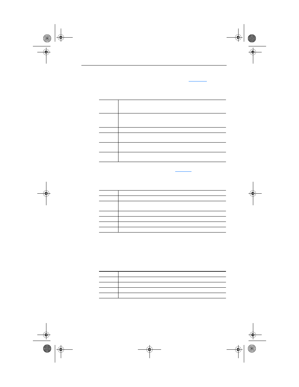
The example ladder logic program simplifies addressing the various PCP
indexes. Before calling the PCP Write Subroutine (
), six
registers are loaded to identify the variable to write:
Table 6.5 PCP Write Main Program Data
The PCP Write Subroutine uses the data in
to create the
following Command Message:
Table 6.6 PCP Write Subroutine Command Message
Note that writing to parameters causes a non-volatile storage (NVS)
write cycle and therefore must NOT be done frequently (can exceed the
maximum number of allowable write cycles and cause the product to
malfunction).
Table 6.7 PCP Write Subroutine Reply Message
N23:0
The Communication Reference (CR) to write to:
Set to “2” to access Station 1.0 (CR=2)
Set to “3” to access Station 2.0 (CR=3)
N23:1
The desired parameter area to be accessed:
Set to “0” for DPI Host parameters
Set to “1” for 20-COMM-I parameters
N23:2
The actual parameter number to write to (1, 2, ....n).
N23:3
The number of bytes of data to write:
Set to either “1” (1 byte), “2” (2 bytes) and “4” (4 bytes)
N23:4
Data Word #1
(1 and 2-byte writes, MSW of 4 byte write).
N23:5
Data Word #2
(LSW of 4-byte write).
N23:10
The PCP Command word (set to “8” for PCP Write).
N23:11
The Command Reference (CR) to write to.
N23:12
The PCP Index of the variable to write (“306Ah” = Host parameter 106,
etc.).
N23:13
Sub Index not used.
N23:14
The number of bytes of data to write (set to “1”, “2” or “4”).
N23:15
Data word 1.
N23:16
Data word 2.
N23:20
= PCP Status Word.
N23:21
= Echo of the Command word (0008h).
N23:22
= Number of words following.
N23:23
= CR.
N23:24
= Result (“0” = good).
20COMM-UM007A-EN-P.book Page 11 Tuesday, January 22, 2002 10:52 AM