Understanding the i/o image, Understanding the i/o image -2 – Rockwell Automation 20-COMM-I Interbus Adapter User Manual
Page 52
5-2
Using I/O Messaging
The terms input and output are defined from scanner’s point of view.
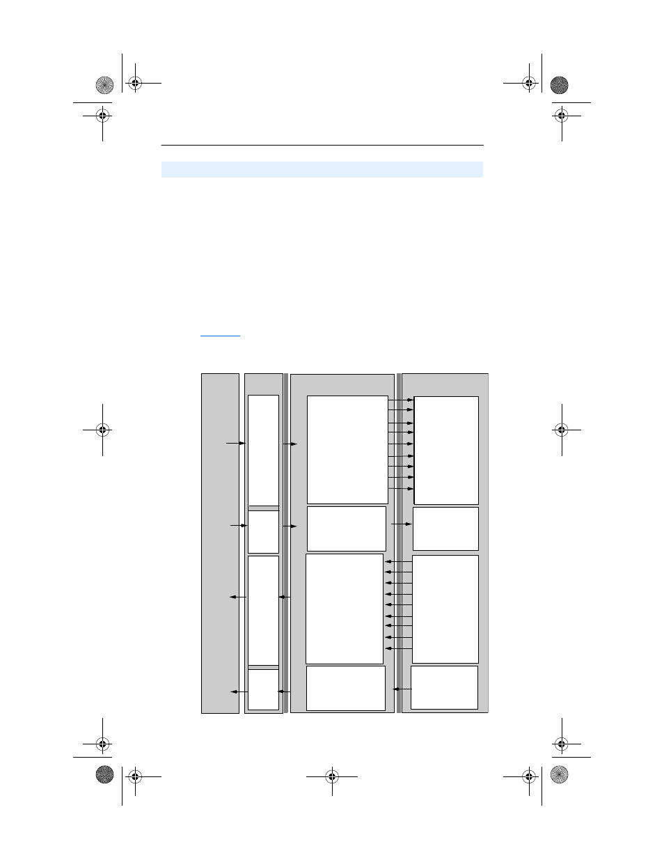
Therefore, Output I/O is data that is output from the scanner and
consumed by the Interbus adapter. Input I/O is status data that is
produced by the adapter and consumed as input by the scanner. The I/O
image table will vary based on the following:
• Size (either 16-bit or 32-bit) of the Reference/Feedback word and
Datalink words used by the drive.
• Configuration of Parameter 8 - [DPI I/O Config] in the adapter. If
all I/O is not enabled, the image table is truncated. The image table
always uses consecutive words starting at word 0.
illustrates an example of an I/O image with 16-bit words.
Figure 5.1 Example I/O Image with All I/O Enabled
Understanding the I/O Image
Controller
Scanner
Adapter
PowerFlex Drive
Interbus
DPI
Output
Image
(Write)
Input
Image
(Read)
0 Logic Status
1 Feedback
2 Datalink Out A1
3 Datalink Out A2
4 Datalink Out B1
5 Datalink Out B2
6 Datalink Out C1
7 Datalink Out C2
8 Datalink Out D1
0 Logic Command
1 Reference
2 Datalink In A1
3 Datalink In A2
4 Datalink In B1
5 Datalink In B2
6 Datalink In C1
7 Datalink In C2
8 Datalink In D1
Logic Status
Feedback
Data Out A1
Data Out A2
Data Out B1
Data Out B2
Data Out C1
Data Out C2
Data Out D1
Word and I/O
Message
Handler
Message
Handler
PCP Communications
PCP Communications
M0/M1
Files
M0/M1
Files
Logic Command
Reference
Data In A1
Data In A2
Data In B1
Data In B2
Data In C1
Data In C2
Data In D1
20COMM-UM007A-EN-P.book Page 2 Tuesday, January 22, 2002 10:52 AM