Rockwell Automation 22-SCM-232 Serial Converter Module User Manual
Page 86
H-2
ControlLogix/CompactLogix Example Ladder Program
Figure H.1 Example ControlLogix Ladder Logic Program
ControlLogix communications to a PowerFlex 4/40 using a 22-SCM-232
The 22-SCM-232 connects directly to the serial port on the processor (DB9 connector) and the RJ45 port on the PowerFlex
4/40. It provides both media (RS232 to RS485) and protocol (DF1 to Modbus RTU) conversions.
Additional PowerFlex 4/40 drives can be added. Use one AK-U0-RJ45-SC1 Splitter Cable for connecting to the first drive,
and one AK-U0-RJ45-TB2P for every drive. The Communication tab in the MSG instruction setup identifies the port to use
and the drive node to communicate with.
PF4 Parameters: 22-SCM-232 Parameters:
36 [Start Source] = 5 (Comm Port) 1 [Adapter Cfg] = RTU Master
38 [Speed Reference] = 5 (Comm Port) 2 [DF1 Addr Cfg] = 1 (this MUST equal Parameter 104 of the PF 4/40 it is
connected to)
103 [Comm Data Rate] = 4 (19.2K) 3 [DF1 Rate Cfg] = 19.2k bps
104 [Comm Node Addr] = 1
107 [Comm Format] = 0 (RTU 8-N-1)
For the PowerFlex 4/40 drives, 19.2K and 8-N-1 are a requirement and can not be changed. The data rate for the controller
and the SCM MUST be equal to each other, but can be set faster or slower than the drives baud rate if desired. It is
recommended that 19.2K be used for ALL serial connections (controller, SCM, and drives) to be consistent and to avoid any
errors.
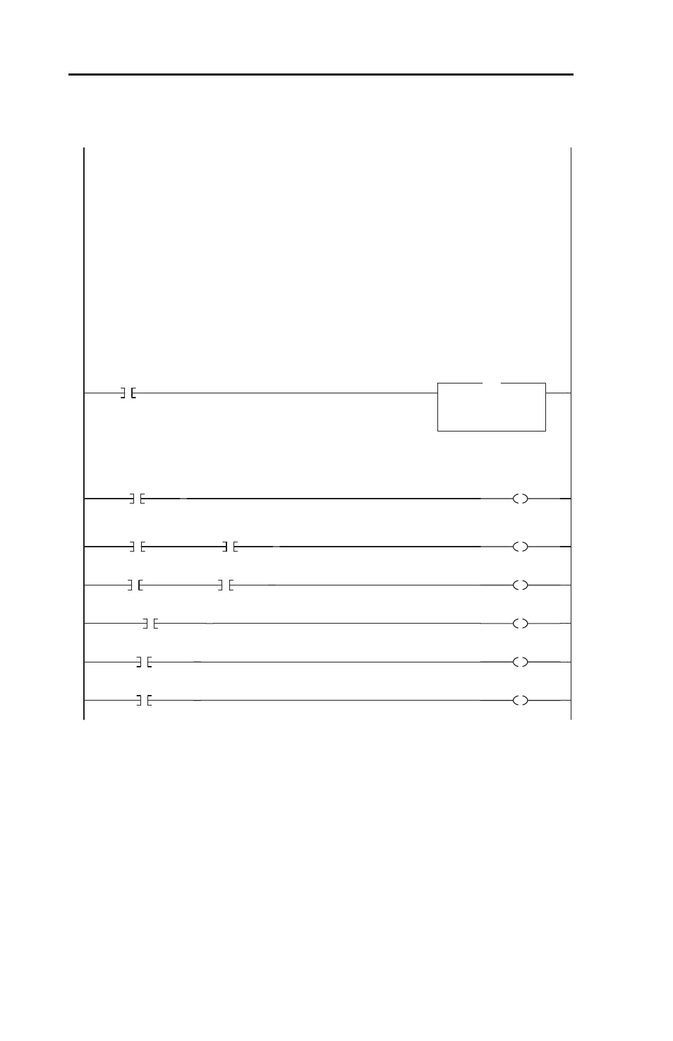
This rung clears the read data are (N7:10-19) on the first program scan (Constant_0 = "0").
0
/
Powerup_1shot
Copy File
Source
Constant_0
Dest DriveReadData[0]
Length
7
COP
ControlLogix communications to a PowerFlex 4/40 using a 22-SCM-232
The 22-SCM-232 connects directly to the serial port on the processor (DB9 connector) and the RJ45 port on the PowerFlex
4/40. It provides both media (RS232 to RS485) and protocol (DF1 to Modbus RTU) conversions.
Additional PowerFlex 4/40 drives can be added. Use one AK-U0-RJ45-SC1 Splitter Cable for connecting to the first drive,
and one AK-U0-RJ45-TB2P for every drive. The Communication tab in the MSG instruction setup identifies the port to use
and the drive node to communicate with.
PF4 Parameters: 22-SCM-232 Parameters:
36 [Start Source] = 5 (Comm Port) 1 [Adapter Cfg] = RTU Master
38 [Speed Reference] = 5 (Comm Port) 2 [DF1 Addr Cfg] = 1 (this MUST equal Parameter 104 of the PF 4/40 it is
connected to)
103 [Comm Data Rate] = 4 (19.2K) 3 [DF1 Rate Cfg] = 19.2k bps
104 [Comm Node Addr] = 1
107 [Comm Format] = 0 (RTU 8-N-1)
For the PowerFlex 4/40 drives, 19.2K and 8-N-1 are a requirement and can not be changed. The data rate for the controller
and the SCM MUST be equal to each other, but can be set faster or slower than the drives baud rate if desired. It is
recommended that 19.2K be used for ALL serial connections (controller, SCM, and drives) to be consistent and to avoid any
errors.
This rung clears the read data are (N7:10-19) on the first program scan (Constant_0 = "0").
This section takes the data from specific tags used elsewhere in the ladder program, and writes them to the respective Logic
Command bits for output to the drive.
1
DriveCommandStop
Logic_Command.0
This section takes the data from specific tags used elsewhere in the ladder program, and writes them to the respective Logic
Command bits for output to the drive.
2
DriveCommandStart
/
DriveCommandStop
Logic_Command.1
3
DriveCommandJog
/
DriveCommandStop
Logic_Command.2
4
DriveCommandClearFaults
Logic_Command.3
5
DriveCommandForward
Logic_Command.4
6
/
DriveCommandForward
Logic_Command.5