Rockwell Automation 22-SCM-232 Serial Converter Module User Manual
Page 63
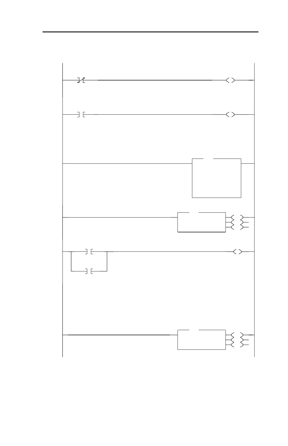
MicroLogix 1200/1500 Example Ladder Program
E-3
Figure E.1 Example MicroLogix 1200/1500 Ladder Logic Program (Continued)
0005
I:0
4
Bul.1764
Fwd / Rev
SS
N7:20
4
Logic Command
FORWARD
0006
I:0
4
Bul.1764
Fwd / Rev
SS
N7:20
5
Logic Command
REVERSE
For demonstration purposes, the value of analog POT0 on the LRP processor is used to generate the
Reference. Since the pot has a range of 0-250 (equates to 0.0 to 25.0 Hz), the pot value is multiplied by 3
to provide a range of 0 to 750 (0.0 to 75.0 Hz). Note that P034 [Minimum Freq] and P035 [Maximum
Freq] on the drive determine the actual output frequency range on the drive. The default is 0.0 to 60.0 Hz.
0007
MUL
Multiply
Source A TPI:0.POT0
0<
Source B
3
3<
Dest
N7:21
336<
MUL
Reference
Write the Logic Command (N182:192) and Reference (N182:193) to the drive.
0008
EN
DN
ER
MSG
Read/Write Message
MSG File
MG11:0
Setup Screen
MSG
Starts the message cycle over again
0009
MG11:0
DN
MG11:0
ER
U
MG11:0
EN
Reads a block of data (starting at N183:198) containing:
N7:10 Logic Status (N183:198)
N7:11 Drive Error Codes (N183:199)
N7:12 Frequency Command (= Reference) (N183:200)
N7:13 Output Frequency (Feedback) (N183:201)
N7:14 Output Current (N183:202)
N7:15 DC Bus Voltage (N183:203)
N7:16 Output Voltage (N183:204)
0010
EN
DN
ER
MSG
Read/Write Message
MSG File
MG11:2
Setup Screen
MSG