Rockwell Automation 22-SCM-232 Serial Converter Module User Manual
Page 54
D-4
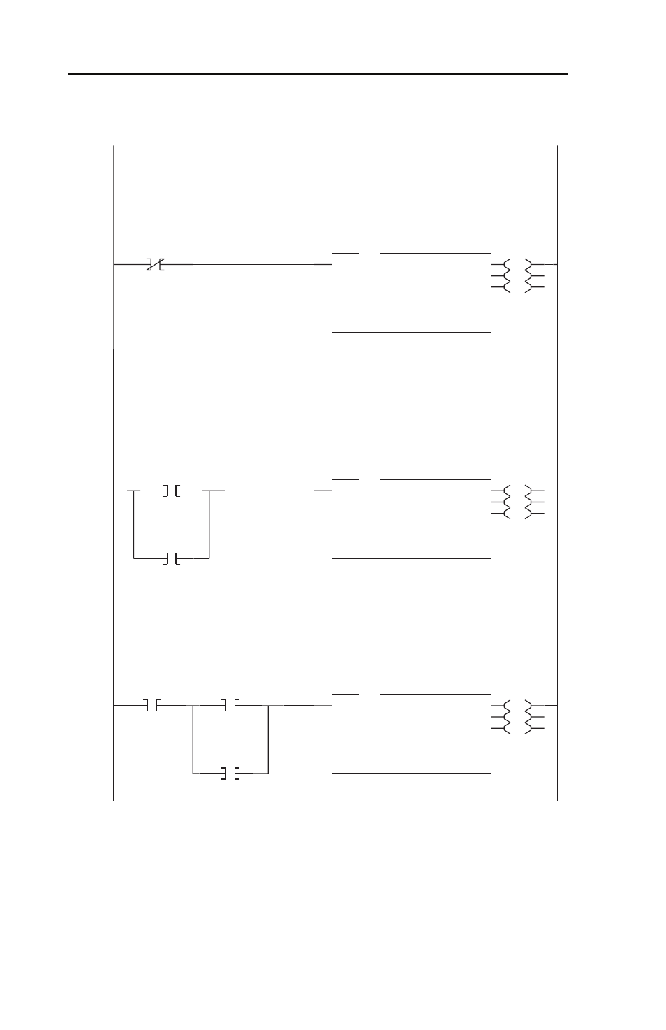
MicroLogix 1000 Example Ladder Program
Figure D.1 Example MicroLogix 1000 Ladder Logic Program (Continued)
Messages must be interlocked and queued to run one at a time. In this example, (4) MSG's are used:
MSG #1 Writes Logic Command and Reference continuously
MSG #2 Reads a block of data, including Logic Status and Feedback, continuously
MSG #3 Writes Parameter 39 [Accel Time 1] on demand (one time per request)
MSG #4 Reads Parameter 39 [Accel Time 1] on demand (one time per request)
Write the Logic Command (N182:192) and Reference (N192:193) to the drive.
0005
S:1
15
First Pass
EN
DN
ER
MSG
Read/Write Message
Read/Write
Write
Target Device
500CPU
Control Block
N7:50
Control Block Length
7
Setup Screen
MSG
After the previous MSG is complete, this MSG reads a block of data (starting at N183:198) containing:
N7:10 Logic Status (N183:198)
N7:11 Drive Error Code (N183:199)
N7:12 Frequency Command (= Reference) (N183:200)
N7:13 Output Frequency (Feedback) (N183:201)
N7:14 Output Current (N183:202)
N7:15 DC Bus Voltage (N183:203)
N7:16 Output Voltage (N183:204)
0006
N7:50
13
Done
(DN)
N7:50
12
Error
(ER)
EN
DN
ER
MSG
Read/Write Message
Read/Write
Read
Target Device
500CPU
Control Block
N7:60
Control Block Length
7
Setup Screen
MSG
If a write is requested elsewhere in the user program (B3:0/0) and the previous MSG is complete, this MSG
will write a value to Parameter 39 - [Accel Time 1]. Uses N150:x addressing, where 'x' equals the
parameter number.
Note: A parameter write causes an EEPROM write cycle on the drive. Do not develop a ladder program
that will perform frequent writes.
0007
B3:0
0
Pr. 39
Write
Request
N7:60
13
Done
(DN)
N7:60
12
Error
(ER)
EN
DN
ER
MSG
Read/Write Message
Read/Write
Write
Target Device
500CPU
Control Block
N7:70
Control Block Length
7
Setup Screen
MSG