Reference materials, Introduction, Operating principle – Rockwell Automation 20L-LL PowerFlex 700L Liquid-to-Liquid Heat Exchanger User Manual
Page 8
P-2
Overview
PowerFlex 700L Liquid-to-Liquid Heat Exchanger User Manual
Reference Materials
The following manuals are recommended for general drive information:
Introduction
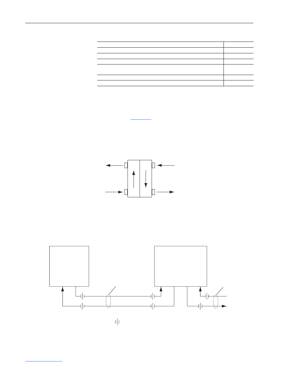
Operating Principle
The operating principle of the heat exchanger is based on liquid-to-liquid
transfer of heat (
Figure P.1
). The drive loop transports the heat load from the
drive to the heat exchanger. The supply loop flows through the heat
exchanger to collect the heat load and transports it to the user’s cooling
system liquid source. The use and choice of a system for disposing of the
heat load is the user’s responsibility.
Figure P.1 Liquid Flow Heat Transfer Diagram
The liquid-to-liquid heat exchanger uses a heat transfer plate to transfer heat
from one liquid to another. This method requires a stable water supply from
the user.
Figure P.2 Drive and Heat Exchanger Plumbing Arrangement
Title Publication
Wiring and Grounding Guidelines for Pulse Width Modulated (PWM) AC Drives
DRIVES-IN001…
Preventive Maintenance of Industrial Control and Drive System Equipment
DRIVES-TD001…
PowerFlex 70/700 Reference Manual
PFLEX-RM001…
Safety Guidelines for the Application, Installation, and Maintenance of Solid State
Control
SGI-1.1
A Global Reference Guide for Reading Schematic Diagrams
0100-2.10
Guarding Against Electrostatic Damage
8000-4.5.2
Drive Loop
Supply Loop
PowerFlex 700L
Drive
Inlet
Drive
Outlet
Hose Kit
= hose or pipe connection
To Facility Water
To
Drive
Inlet
From
Drive
Outlet
Return
To
Supply
In
From
Supply
Liquid-to-Liquid
Heat Exchanger
Customer
Supplied Piping