Control wiring, Control wiring -12 – Rockwell Automation 20L-LL PowerFlex 700L Liquid-to-Liquid Heat Exchanger User Manual
Page 22
1-12
Installation
PowerFlex 700L Liquid-to-Liquid Heat Exchanger User Manual
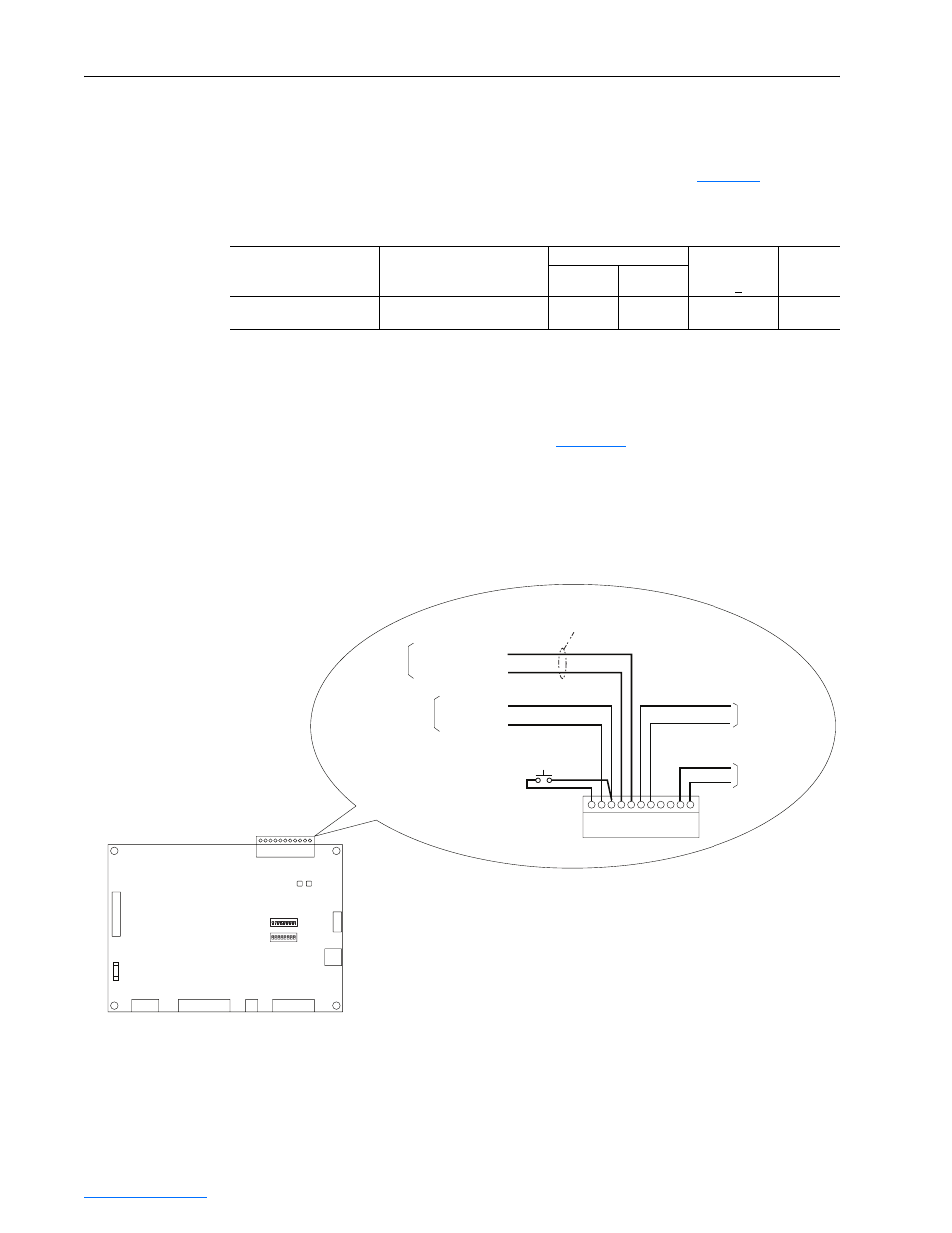
Control Wiring
Connect “run” and “interlock” control wiring from the PowerFlex 700L
drive to the J1 connector on the control board. Refer to
terminal specifications.
Table 1.F Control Board Terminal Specifications
Run Wiring
The run output signal from the PowerFlex 700L drive must be connected to
the heat exchanger control board (
) so that the heat exchanger
automatically starts when the drive is started.
The heat exchanger J1 connector provides fault and alarm contact outputs to
monitor the operating state of the heat exchanger if desired.
Figure 1.9 Control Run Wiring
Name
Description
Wire Size Range
(1)
Recommended
Tightening
Torque (+10%)
Wire Strip
Length
Maximum
Minimum
Coolant Controller Control
Wiring Terminal Block — J1
Control wiring for run, fault and
alarm (optional), and interlock
3.3 mm
2
(#12 AWG)
0.2 mm
2
(#24 AWG)
0.55 N-m
(5 lb.-in.)
7 mm
(0.3 in.)
(1)
Maximum/minimum sizes that the terminals will accept - these are not recommendations.
J2
J1
J3
S1
Heat Exchanger
Control Board
S2
J4
J8
J7
J6
J5
FU1
1
9
1
5
1
2
3
4
5
6
7
8
9
10
1
10
1
8
11
1
2
3
4
5
6
7
8
9
10
11
12V Common
120 VAC
PRIME SWITCH
(on electrical box cover)
+12 VDC
Run
Neutral
To Converter TB5-1
To Converter TB5-3
Frame
3A/3B
Drive
To TB1 (1b-5)
To TB1 (1b-6)
Frame 2
Drive
N.O.
Com
Alarm Contact
(30 VDC @
10A Max.)
N.C.
Com
Fault Contact
(30 VDC @
10A Max.)
J1