Setting the dip switches, S1 dip switch settings, Setting the dip switches -14 – Rockwell Automation 20L-LL PowerFlex 700L Liquid-to-Liquid Heat Exchanger User Manual
Page 24: S1 dip switch settings -14
1-14
Installation
PowerFlex 700L Liquid-to-Liquid Heat Exchanger User Manual
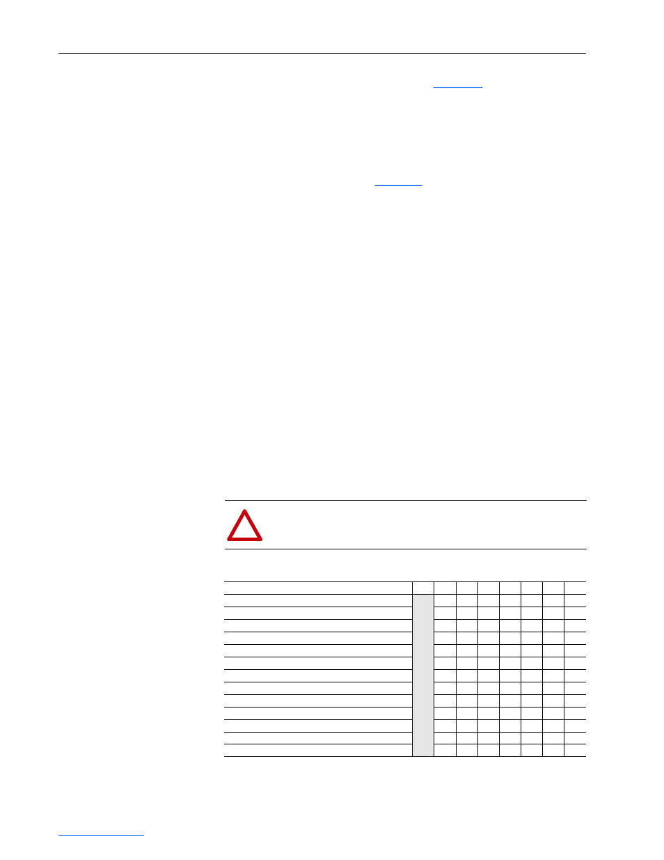
Setting the DIP Switches
Two 8-position DIP switches (S1 and S2 in
Figure 1.7
) set the various
operating functions for the coolant controller. The DIP switch settings may
be changed at any time while power is applied. A “1” indicates the switch is
in the ON (down) position.
S1 DIP Switch Settings
See the descriptions below and
Table 1.G
for S1 switch settings:
• SW1, SW2, and SW3 (Temperature Setpoint) — Sets the temperature at
which the drive loop coolant is maintained by the heat exchanger. The
setpoint can be based on ambient temperature or the alarm temperature.
For example, when set to T
ambient
+ 3°C, the heat exchanger will
attempt to maintain the drive loop coolant at a temperature 3°C above
ambient. When set to T
alarm
- 5°C, the heat exchanger will attempt to
maintain the drive loop coolant at a temperature 5°C below the alarm
temperature which is set by SW6 and SW7.
• SW4 and SW5 (Mode) — Sets the mode of operation for the heat
exchanger. The mode must be set to “1” (Motor Operated Valve) for the
liquid-to-liquid heat exchanger to operate correctly. In mode “0” (on/
off), the run digital input turns the heat exchanger pump on or off.
Modes “2” (2-level) and “3” (3-level) can be used to turn on 2 and 3
solenoids, respectively — and are intended for use with a liquid-to-air
heat exchanger to control the number of fans that are running.
• SW6 and SW7 (Temperature Alarm) — Sets the alarm temperature for
drive loop coolant. When the alarm temperature is reached, the status
LED will flash amber. When the drive loop coolant drops to 2°C below
the alarm temperature, the alarm will automatically reset.
!
ATTENTION: Since the heat exchanger pump continues to
run during an alarm, it is the user’s responsibility to analyze the
alarm condition and take appropriate action.
Table 1.G S1 DIP Switch Settings
Function
SW8 SW7 SW6 SW5 SW4 SW3 SW2 SW1
Temperature Setpoint: T
ambient
(default)
Not Used
—
—
—
—
0
0
0
T
ambient
+3°C
—
—
—
—
0
0
1
T
ambient
+6°C
—
—
—
—
0
1
0
T
ambient
+10°C
—
—
—
—
0
1
1
T
alarm
-5°C
—
—
—
—
1
0
0
Mode: 0 (on/off)
—
—
0
0
—
—
—
1 (Motor Operated Valve - default)
(1)
(1)
Mode switches SW4 and SW5 must be set to mode “1” (Motor Operated Valve) for correct operation of the
liquid-to-liquid heat exchanger.
—
—
0
1
—
—
—
2 (2-level)
—
—
1
0
—
—
—
3 (3-level)
—
—
1
1
—
—
—
Temperature Alarm: 45°C (default)
0
0
—
—
—
—
—
55°C
0
1
—
—
—
—
—
65°C
1
0
—
—
—
—
—
75°C
1
1
—
—
—
—
—