Removing top and side panels, Removing top and side panels -8 – Rockwell Automation 20L-LL PowerFlex 700L Liquid-to-Liquid Heat Exchanger User Manual
Page 18
1-8
Installation
PowerFlex 700L Liquid-to-Liquid Heat Exchanger User Manual
pressure drop of 5.00 to 6.00 PSI on the supply side, and flow must be
provided per
Table 1.D
.
Connect the two supply loop hoses from the heat exchanger to the supply
source.
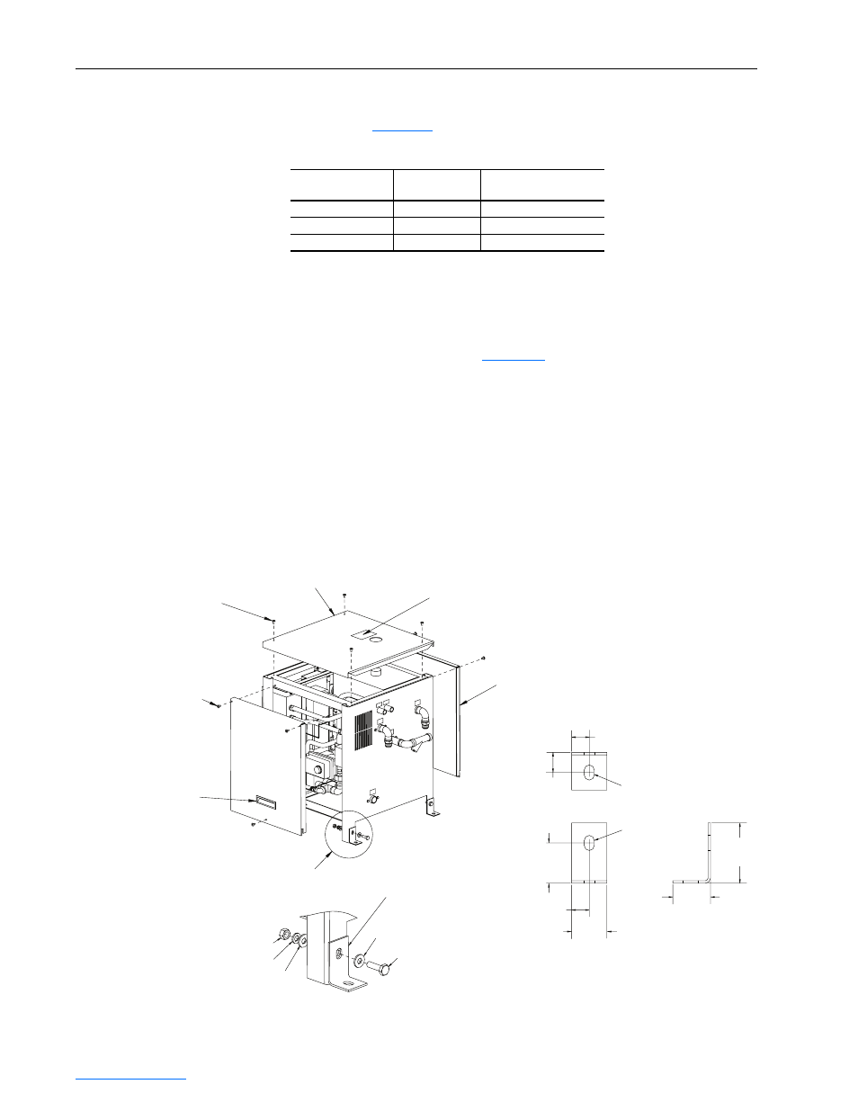
Removing Top and Side
Panels
The top panel and side panels (
Figure 1.5
) can be removed from the heat
exchanger to access internal components. To do so, proceed in this order:
1. Remove the fill tube cap from the top of the tank.
2. Remove the top panel by loosening four captive hardware screws.
3. Remove each side panel by unfastening/removing two sheet metal
screws and loosening one captive hardware screw. Then use the flush
handle to lift the side panel up and out.
Figure 1.5 Top and Side Panel Removal
Table 1.D Supply Loop Minimum Flow Rates
Heat Exchanger
Drive Size
Minimum Supply Loop
Flow Rate
20L-LL13K-P75A
Frame 2
15.1 LPM (4 GPM)
20L-LL13K-P75A
Frame 3A
22.7 LPM (6 GPM)
20L-LL24K-1P0A
Frame 3B
56.8 LPM (15 GPM)
FILL TUBE WARNING:
Fill with approved fluid or
equipment damage may result.
See Instruction Manual.
M10 x 1.5 x 35
Hexagonal Head Screw
M10 x 1.5 Nut
See DETAIL A
Top Panel
Flush Handle
(2 places)
Sheet Metal Screw
(4 places)
Side Panel
(2 places)
25.4
(1.0)
50.8
(2.0)
22.2
(0.88)
44.5
(1.75)
47.6
(1.88)
76.2
(3.0)
22.2
(0.88)
22.2 x 12.7
(0.875 x 0.5) Slot
22.2 x 12.7
(0.875 x 0.5) Slot
M10 Lock Washer
M10 Flat Washer
M10 Flat Washer
Shipping/Field Installation
Mounting Angle (4 places)
DETAIL A
Captive Hardware
(6 Places)
Dimensions are in
millimeters and (inches).