Chapter 1, Installation, Installation specifications – Rockwell Automation 20L-LL PowerFlex 700L Liquid-to-Liquid Heat Exchanger User Manual
Page 11: Required ambient conditions, Location requirements, Installation specifications -1
PowerFlex 700L Liquid-to-Liquid Heat Exchanger User Manual
Chapter
1
Installation
This chapter provides information on installing and wiring the PowerFlex
700L Liquid-to-Liquid Heat Exchanger.
Installation Specifications
Required Ambient Conditions
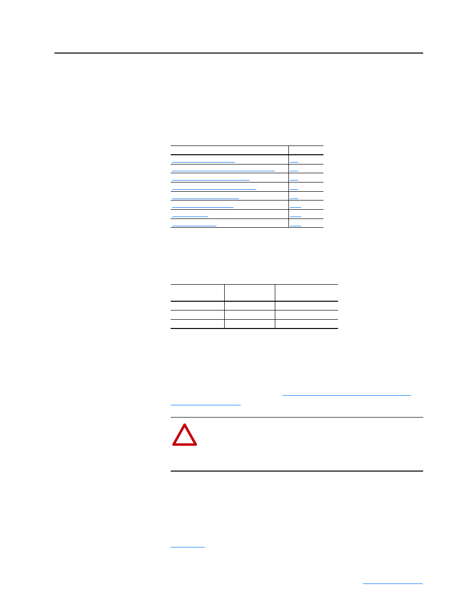
The heat exchanger is designed to work within these ambient temperatures:
It is the user’s responsibility to ensure that the temperature remains within
this limit during operation. Condensation cannot be allowed to form in the
drive. The easiest way of preventing condensation inside the drive is by
keeping the water temperature in the supply loop higher than the ambient
temperature. Circulate coolant through the drive only when the drive is
powered – except as described in
Adding Coolant to the Drive Loop for
Location Requirements
Place the heat exchanger in a suitable location not more than 9.1 m (30 feet)
from the drive. The location must be on the same level (altitude) as the drive
to prevent increasing the load on the heat exchanger coolant pump. Refer to
Figure 1.1
for overall dimensions of the heat exchanger and locations of
hose connections for the drive loop and supply loop.
For information on…
See page…
Connecting Hoses to the Heat Exchanger
AC Supply Source Considerations
Heat Exchanger
When Used With
Drive Size
Ambient
Temperature Range
20L-LL13K-P75A
Frame 2
0-50°C (32-122°F)
20L-LL13K-P75A
Frame 3A
0-40°C (32-104°F)
20L-LL24K-1P0A
Frame 3B
0-40°C (32-104°F)
!
ATTENTION: Risk of equipment damage exists. Failure to
keep the coolant temperature in the drive loop higher than the
ambient temperature may result in condensation accumulating on
the drive heatsink and/or circuit boards, which could damage the
drive.