Connecting two separate networks together – Weidmuller WI-MOD-945-E: 900Mhz Wireless Ethernet & Device Server v2.16 User Manual
Page 75
Weidmuller Wireless Ethernet Modem & Device Server WI-MOD-945-E User Manual
Page 75
www.weidmuller.com
Rev 2.136
Ensure the ESSID and Radio Encryption method match the Access Point.
If encryption is used, ensure the encryption keys or passphrase match the Access Point.
Client 2 Configuration
As above, however set the Ethernet and Wireless IP addresses as 192.168.0.202
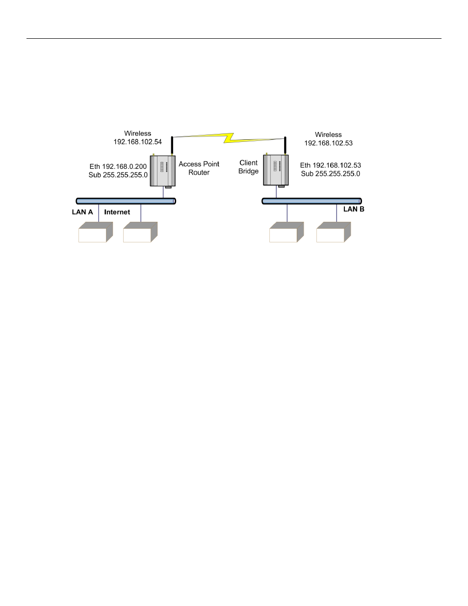
Connecting two separate networks together
LAN A Configuration
In this example, network A is connected to the internet via a router at IP address 192.168.0.1.
Devices on LAN A that only require access to devices on LAN A and B, should have their gateway IP address set to the
WI-MOD-945-E Access Point as 192.168.0.200.
Devices on LAN A, that must interact with devices on LAN A and B and the internet should set the internet router
192.168.0.1 as their gateway, and must have a routing rule established for devices on Network B. On PCs, this may be
achieved with the MS-DOS command ROUTE. For this example use: ROUTE ADD 169.254.102.0 MASK 255.255.255.0
192.168.0.200
. For more information on the DOS “Route” command see section 4.10 - “Utilities”
LAN B Configuration
All devices on LAN B should be configured so their gateway IP address is that of the WI-MOD-945-E Access Point as
169.254.102.54
Access Point Configuration
Connect straight through Ethernet cable between PC and WI-MOD-945-E.
Ensure configuration PC and WI-MOD-945-E are setup to communicate on the same network
Set dipswitch to SETUP
Power up unit, and wait for LINK led to cease flashing.
Adjust PC network settings
Set Configuration PC network card with network setting of IP address 192.168.0.1, netmask 255.255.255.0
Open configuration webpage with Internet Explorer at address 192.168.0.1XX/
When prompted for password, enter default username “user” and password “user”
Enter “Network”, and select Operating Mode as Access Point.
Device Mode should be set to Router.
Set the Gateway IP address to 192.168.0.1
Figure 58 - Example Config 2