Line-of-sight installations, Antennas, Installation tips – Weidmuller WI-MOD-945-E: 900Mhz Wireless Ethernet & Device Server v2.16 User Manual
Page 15
Weidmuller Wireless Ethernet Modem & Device Server WI-MOD-945-E User Manual
Page 15
www.weidmuller.com
Rev 2.136
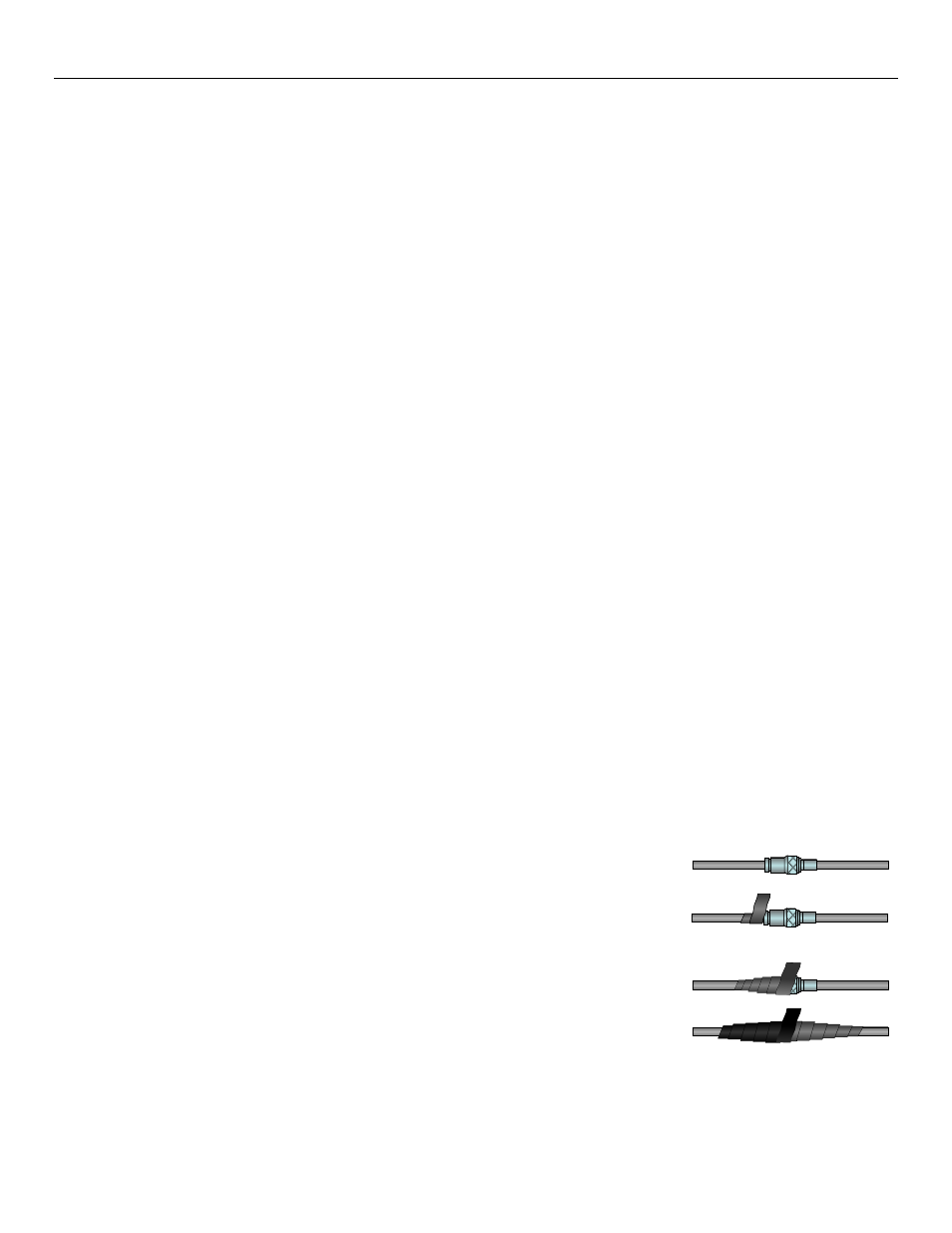
Stretch to elongate sealant tape
while wrapping over the connection
For proper UV protection Electrical
Tape should then be wrapped over
the Vulcanising Tape
problem. However where the radio path changes because the WI-MOD-945-E is mounted on moving equipment, or if
there is moving equipment in the area, then the solution is to use two antennas. Because the two connectors are
separated, the RF signal at each connector will be different in the presence of multi-path fading. The WI-MOD-945-E unit
will automatically select the higher RF signal provided RX diversity has been enabled on radio Config page.
Line-of-sight installations
In longer line-of-sight installations, the range may be increased by using a high gain antenna on the TX/RX connector.
However, the gain should not cause the effective radiated power (ERP) to exceed the permitted value. A second higher
gain antenna can be connected to the RX connector without affecting ERP - this will increase the operating range
provided any interference in the direction of the link is low.
Antennas
Antennas can be either connected directly to the module connectors or connected via 50 ohm coaxial cable (e.g. RG58
Cellfoil or RG213) terminated with a male SMA coaxial connector. The higher the antenna is mounted, the greater the
transmission range will be, however as the length of coaxial cable increases so do cable losses.
The net gain of an antenna/cable configuration is the gain of the antenna (in dBi) less the loss in the coaxial cable (in dB).
The WI-MOD-945-E maximum net gain for US and Canada is 10dB (4W ERP) and 0dB for Australia and NZ (1 W ERP).
There is no gain restriction for antennas connected to the RX connector
unless “TX Diversity” is enabled on the Radio
page.
The gains and losses of typical antennas are
Antenna
WI-MOD-945-E Gain (dBi)
Dipole
0 dB
Collinear
5 or 8 dBi
Directional
10
– 15 dBi
Cable Loss
dB per 30 m / 100 ft
RG58 Cellfoil
-9 dB
RG213
-7.4 dB
LDF4-50
-2 dB
The net gain of the antenna/cable configuration is determined by adding the antenna gain and the cable loss.
For example, an 8dBi antenna (5.8dBd) with 10 meters of Cellfoil (3dBd) has a net gain of 2.8dB (5.8dB
– 3dB).
Installation tips
Connections between the antenna and coaxial cable should be carefully taped to
prevent ingress of moisture. Moisture ingress in the coaxial cable is a common cause
for problems with radio systems, as it greatly increases the radio losses. We
recommend that the connection be taped, firstly with a layer of PVC Tape, then with a
vulcanizing tape such as “3M 23 tape”, and finally with another layer of PVC UV
Stabilized insulating tape. The first layer of tape allows the joint to be easily inspected
when trouble shooting as the vulcanizing seal can be easily removed.
Where antennas are mounted on elevated masts, the masts should be effectively
earthed to avoid lightning surges. For high lightning risk areas, approved
WEIDMULLER surge suppression devices
such as the “CSD-SMA-2500” or “CSD-N-
6000” should be fitted between the module and the antenna. If using non
WEIDMULLER surge suppression devices then the devices must have a 'TURN ON' voltage of less than 90V If the
Figure 1 - Vulcanizing Tape