Instruction sheet – Prescolite 37G-TP-1, 2 & 4 User Manual
Page 2
www
.prescolite.com
• Prescolite
TollFree
Technical Support
1.888.PRS.4TEC
• Hours: 8am - 5pm ET
101 Corporate Drive • Spartanburg, SC 29303
With representatives offices in principal cities throughout North America.
Copyright 2005, 08/05 revision, All Rights Reserved - Printed in U.S.A.
Part No. . . . . . . . . . . . . . . . . . . . . . . . . . . . . . . . .03214500
Instruction
Sheet
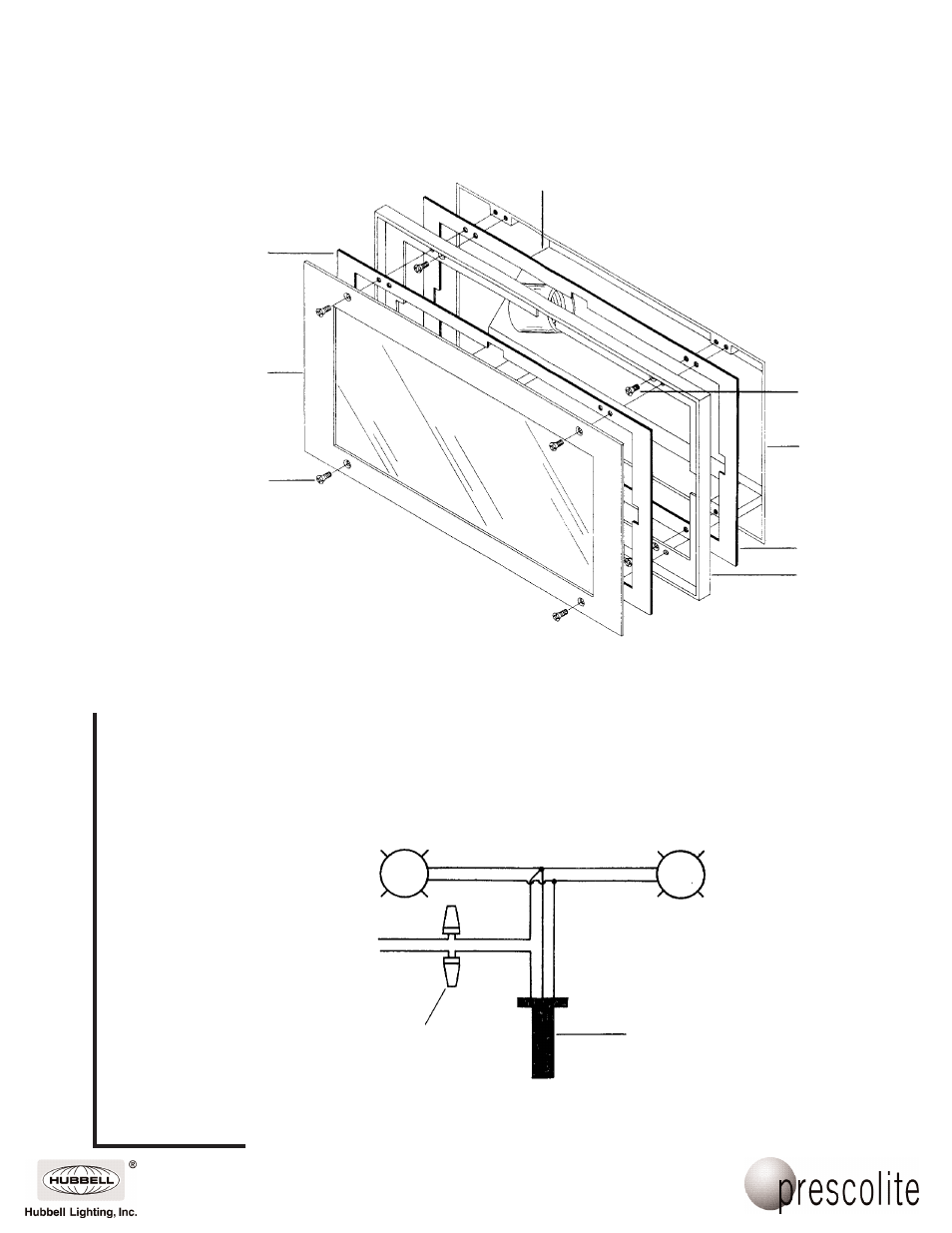
Socket Holder
Plate
Housing
(Installed)
Faceplate
(37-4)
6-32 x 3/8 Flat
Head Screw (4)
Faceplate Installation
Fig. 3
5. Make electrical connections. Connect ground wires to green ground leads. Connect white
(common) to white leads. Connect power supply (line) to black leads (see wiring diagram Fig. 4)
and push splices into J-Box. Assemble ground wire to ground screw in the housing. Replace the
socket mounting plate and install the lamps.
WARNING: DO NOT pinch wires.
Consult a qualified Electrician for all other options that require other wiring configurations.
6. Assemble the gasket and faceplate to the housing as shown in Fig. 3 with (4) 6-32 x 3/8 flathead
screws, (provided in packet).
6-32 x 1/4 Flat
Head Screw (4)
Gasket
Trim Ring
Gasket
Wire Nut
(By Others)
(Blk.)
120V
Supply
(Wht.)
Thermal
Protector
Wiring Diagram
Fig. (4)
L
L