Prescolite HV HID CYLINDERS User Manual
Ins tru ctio n s he et, Installation instructions hc/hd/hv hid cylinders
Ins
tru
ctio
nS
he
et
w
w
w
.p
r
e
s
c
o
li
te
.c
o
m
•P
res
co
lite
To
llF
ree
Te
ch
nic
al
Su
pp
ort
1.8
88
.P
RS
.4T
EC
•
Ho
urs
:8
am
-5
pm
ET
Part No. . . . . . . . . . . . . . . . . . . . . . . . . . . . . . . . .05296800
Ins
tru
ctio
nS
he
et
INSTALLATION INSTRUCTIONS
HC/HD/HV HID CYLINDERS
A. SURFACE MOUNT
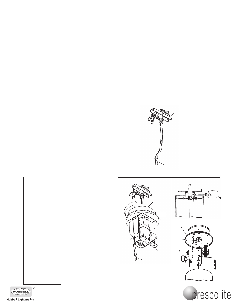
1. Secure mounting channel assembly to a 3 1/2"or 4" octagonal box
(Fig. 1). End slots in channel are provided for additional security, and
additional bolts through these slots are recommended for applications
where winds, vibration, or earthquakes may be encountered. Make
electrical connections in outlet box.
2. (HV cylinder only) Loosen both socket bracket mounting screws and
swing socket bracket toward capacitor bracket (Fig. 2b).
3. Feed channel assembly leads into luminaire top assembly. Engage
running thread and rotate assembly a few times. Make sure leads are
hanging freely on one side of the lamp socket bracket (Fig. 2). Rotate
assembly until canopy contacts ceiling.
a. (HC/HD cylinder) Assembly may be locked to running thread by
tightening the set screw (Fig. 2a).
b. (HV cylinder) Pull engaged end of socket bracket down slightly ans
swing bracket past mounting screw toward ballast. Tighten thread
clamp screw to running thread. Return socket bracket to original
position and tighten screws (Fig. 2b).
4. Make electrical connections inside fixture. Splice ground wire to fixture
ground wire, splice white supply lead to white fixture lead labeled
‘com’, splice black supply lead to black fixture lead labeled ‘line’.
B. PENDANT MOUNT
1. Secure pendant mount assembly to 3 1/2", or 4" octagonal box (Fig.
3). End slots in casting are provided for additional security, and
additional bolts through these slots are recommended for applications
where winds, vibration, or earthquakes may be encountered. Make
electrical connections in outlet box.
2. With HV cylinders, loosen both socket bracket mounting screws and
swing socket bracket toward capacitor bracket (Fig. 2b).
3. Rest canopy on luminaire top assembly. Feed pendant assembly 4"
into luminaire top assembly. Engage pendant thread and rotate
assembly a few times. Make sure leads are hanging freely on one
side of the lamp socket bracket (Fig. 3). Rotate assembly until
pendant threads are fully engaged.
a. (HC/HD cylinder) Assembly may be locked to running thread by
tightening the set screw (Fig. 3a).
b. (HV cylinder) Pull engaged end of socket bracket down slightly ans
swing bracket past mounting screw toward ballast. Tighten thread
clamp screw to running thread. Return socket bracket to original
position and tighten screws (Fig. 3b).
4. Make electrical connections in fixture. Splice ground wire to fixture
ground wire, splice white supply lead to white fixture lead labeled
‘com’, splice black supply lead to black fixture lead labeled ‘line’. (see
Fig. 3). Replace housing and reflector and install proper lamp (Fig. 4).
5. If luminaire is not hanging straight, loosen the four ball clamp screws
in pendant casting (see Fig. 3). Align luminaire and retighten screws.
6. Install canopy.
7. If installed in windy areas, or in areas subject to vibration or
earthquakes, a safety chain or cable is recommended (by others).
Fig. 1
Rotate
Canopy
Mounting Channel
Channel Assembly Leads
Fig. 2a
Fig. 2b
Fig. 2
Channel
Assembly
Leads
Luminaire Top
Assembly
Capacitor
Bracket
Thread
Clamp
Socket
Bracket
Set Screw
NOTE: For surface and pendant mounting configurations first remove reflector by loosening two retaining screws.
Rotate reflector to disengage and remove, then remove housing cylinder.
IMPORTANT SAFETY INFORMATION. READ AND FOLLOW ALL SAFETY INSTRUCTIONS. Follow label information
and instructions concerning Wet or Damp Locations, installation near combustible materials, insulation, building materials,
and proper lamping. Do not install in areas subject to combustible vapors or gases. Before wiring to power supply and
during servicing or relamping, turn off power at fuse or circuit breaker. All servicing or relamping must be performed by
qualified service personnel. Product must be grounded to avoid potential electric shock or other potential hazard.
Product must be mounted in locations and at heights and in a manner consistent with its intended use, and in
compliance with the National Electrical Code and local codes. The use of accessory equipment not recommended by
the manufacturer or installed contrary to instructions may cause an unsafe condition. Do not block light emanating from
product in whole or part, as this may cause an unsafe condition. Do not allow items such as drapes, curtains, screens or
the like to come into contact with the product or to block light from the product, as this may cause an unsafe condition.
701 Millennium Boulevard • Greenville, SC 29607
With representatives offices in principal cities throughout North America.
Copyright 2007, 02/07 revision, All Rights Reserved - Printed in U.S.A.