Prescolite DLHL User Manual
Instruction sheet, Assembly & installation instructions, Dlhl
Instruction
Sheet
www
.prescolite.com
Prescolite T
oll Free T
echnical Suppor
t 1.888.PRS.4TEC
Hours: 8am-5pm ET
701 Millennium Blvd., Greenville, SC 29607
With representatives offices in principal cities throughout North America
Copyright ©2013, 7/19/13 All rights reserved • Printed in the USA All rights reserved • Printed in the USA
1
Instruction
Sheet
www
.prescolite.com
Prescolite T
oll Free T
echnical Suppor
t 1.888.PRS.4TEC
Hours: 8am-5pm ET
Part Number 93014983
Instruction
Sheet
www
.prescolite.com
Prescolite T
oll Free T
echnical Suppor
t 1.888.PRS.4TEC
Hours: 8am-5pm ET
Instruction
Sheet
www
.prescolite.com
Prescolite T
oll Free T
echnical Suppor
t 1.888.PRS.4TEC
Hours: 8am-5pm ET
IMPORTANT SAFETY INFORMATION. READ AND FOLLOW SAFETY INSTRUCTIONS. Follow label information
and instructions concerning wet or damp locations, installation near combustible materials, insulation, building materials, and
proper lamping. Do not install in areas subject to combustible vapors or gases. Before wiring to power supply and during
servicing or relamping, turn off power at fuse or circuit breaker. All servicing or relamping must be performed
by qualified service personnel. Product must be grounded to avoid potential electric shock or other
potenial hazard. Product must be mounted in locations and at heights in a manner consistent with
its intended use, an in compliance with the National Electrical Code and local codes. The use of accessory
equipment not recommended by the manufacturer or installed contrary to instructions may cause an unsafe condition. Do not black
light emanating from product in whole or part, as this may cause an unsafe condition. Do not allow items such as drapes, curtains,
screens, or the like to come into contact with the product or to block light from the product, as this may cause an unsafe condition.
INSTALLATION INSTRUCTIONS
DLHL
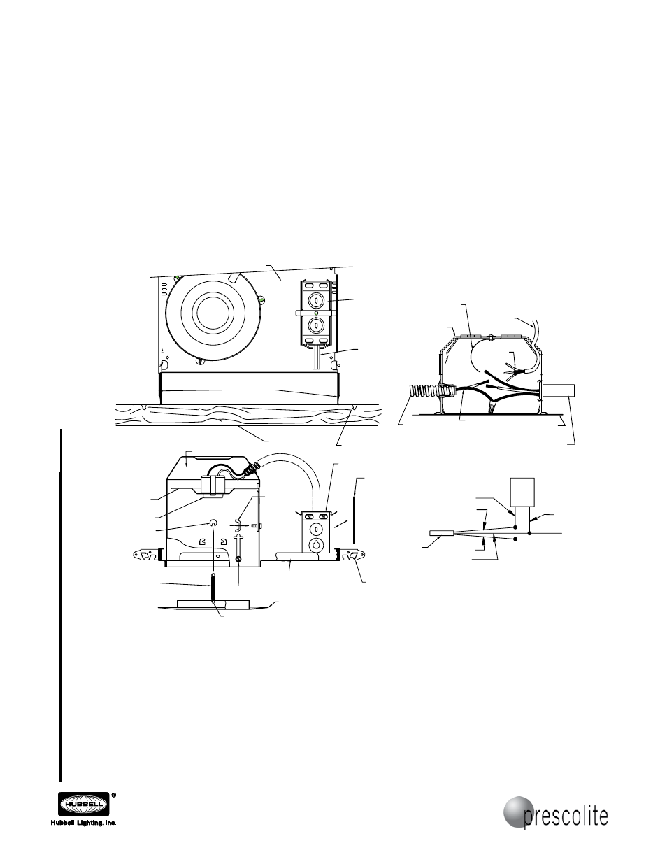
FIGURE 1
FIGURE 3
COVER
PLATE
(3) SHEET METAL SCREWS
NOTE: IF 12 GA. OR 14 GA. TYPE NM CABLE (ROMEX)
IS USED, THEN ONLY (1) CABLE PER SIDE OF
JUNCTION BOX IS ALLOWABLE.
Assembly & Installation Instructions
CAUTION:
Read instructions carefully and turn electricity off at main
circuit breaker panel before beginning installation.
6952TG
SPEC.NO.023502 (01-19-99)
2. REMOVE COVER PLATE FROM JUNCTION BOX. SLIP TYPE NM CABLE (ROMEX) THROUGH DESIRED HOLE IN JUNCTION BOX ABOVE
RETAINING PLATE. CONNECT SUPPLY WIRES AS SHOWN IN WIRING DIAGRAM. REPLACE COVER.
3. IF OTHER THAN TYPE NM CABLE (ROMEX) IS TO BE USED, REMOVE ONE LARGE KNOCKOUT AT DESIRED LOCATION ON TOP OR
SIDES OF JUNCTION BOX. FASTEN APPROPRIATE UL LISTED CONNECTOR (NOT FURNISHED) WITH ELECTRICAL SUPPLY CABLE IN
JUNCTION BOX
(SEE FIGURE 2).
4. HOUSING CAN NOW BE ADJUSTED TO CEILING LEVEL BY LOOSENING THREE (3) SHEET METAL SCREWS AND RAISING OR LOWERING
HOUSING THEN TIGHTENING SCREWS
(SEE FIGURE 3).
5. TO ADJUST SOCKET BRACKET, LOOSEN WING NUT AND SLIDE BRACKET UP OR DOWN TO CORRECT POSITION. TIGHTEN WING NUT
WHEN COMPLETE.
WARNING: Use only those trims, lamps and maximum wattages proper for this fixture, as indicated on the label within the fixture housing.
WARNING: The National Electrical Code, Article 110-3 (b), states that "Listed or labeled equipment shall be used or installed
in accordance with any instructions included in the listing or labeling". Use only with Progress UL listed trims. Use of other
trims not listed in this fixture, including those that are UL classified, is a violation of N.E.C. 110-3(b) and voids all warranties.
WARNING: If any special control devices are used with this fixture, follow the instructions carefully to assure full compliance
with N.E.C. requirements. If there are any questions, contact a qualified Electrical Contractor.
WARNING: (RISK OF FIRE): Recessed portions of recessed housing, other than at points of support, shall be spaced at least
1/2 inch from combustible material. Thermal insulation shall not be installed within three (3) inches of recessed housing,
or junction box, and shall not be so installed above the fixture, as to entrap heat and prevent the free circulation of air.
FIGURE 2
TYPE NM CABLE
(ROMEX)
CONDUIT
FROM HOUSING
FIXTURE
WIRES
FIXTURE GROUND
WIRE
WIRE RETAINING
PLATE
JUNCTION
BOX
PLASTER
FRAME
SOCKET
WHITE
BLACK
WHITE
BLACK
BLACK
BLUE
WHITE
INSULATION
SENSOR
SUPPLY
WIRES
INSULATION
SENSOR
WOOD JOIST
BAR HANGERS
BAR HANGER TAB
PLASTER FRAME
JUNCTION BOX
HOUSING
SOCKET
SOCKET
BRACKET
WING NUT
PLASTER FRAME
BAR HANGER TAB
JUNCTION BOX
INSULATION
SENSOR
1. SLIP BAR HANGERS THROUGH SLOTS IN PLASTER FRAME. HOLD FRAME IN DESIRED LOCATION BETWEEN JOISTS AND DRIVE BAR
HANGER TABS INTO WOODEN JOISTS. USE NAILS THROUGH HOLES IN HANGER ENDS FOR ADDITIONAL SUPPORT IF NECESSARY.
INSTALL LOCKING SCREWS INTO PLASTER FRAME AND TIGHTEN AGAINST BAR HANGERS TO PREVENT LATERAL MOVEMENT OF
FRAME
(SEE FIGURE 1).
TRIM
RETAINING
SPRINGS
SPRING HOLE
LANCE
6. HOOK RETAINING SPRINGS INTO LANCES IN TRIM
(SEE FIGURE 3). STRETCH RETAINING SPRINGS INTO SPRING HOLES IN HOUSING.
PUSH TRIM ASSEMBLY UP INTO HOUSING UNTIL LIP ON TRIM PRESSES UP AGAINST CEILING.
7. INSTALL LAMP (NOT FURNISHED).
CAUTION:- ALL GLASS IS FRAGILE, USE CARE WHEN
HANDLING LAMP.