Instruction sheet, Prs.4tec – Prescolite Recessed HID User Manual
Page 2
www
.prescolite.com
• Prescolite
TollFree
Technical Support
1.888.PRS.4TEC
• Hours: 8am - 5pm ET
101 Corporate Drive • Spartanburg, SC 29303
With representatives offices in principal cities throughout North America.
Copyright 2005, 08/05 revision, All Rights Reserved - Printed in U.S.A.
Part No. . . . . . . . . . . . . . . . . . . . . . . . . . . . . . . . .05064500
Instruction
Sheet
5. Connect the mate-n-lock connector from the ballast to the connector from the fixture. Push all connectors and splices back into the
J-Box.
6. Place the ballast retaining strap into the ‘T’ slot in the bracket as shown. Place the ballast on the bracket so it rests against the side
of the J-Box and one of the ballast mounting holes is positioned over the screw inside the J-Box to prevent ballast movement. Wrap
the retaining strap around the ballast and secure it with the draw latch (see Fig. 5)
CAUTION: Do not attempt to modify or rewire factory-installed wiring on the fixture or ballast. Safety and proper operation of the fixture
depend on the integrity of the wiring.
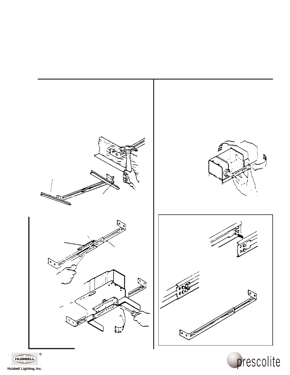
FIXTURE INSTALLATION
1. Nail one B6 bar hanger to ceiling joist (Fig. 1), or attach to
suspended ceiling support member with clamps in Packet
94 (Fig. 2). Standard 1 1/2" carrier channels can be used to
install fixture.
2. Assemble other bar hanger to fixture by placing in ‘C’
bracket and pry locking tabs on ‘C’ bracket against bar
hanger (Fig. 3).
3. To install fixture, position ‘C’ bracket on fixture over the bar
hanger previously installed in ceiling.
4. Attach bar hanger on fixture to ceiling structure.
5. Position fixture and lock in place by prying locking tabs
on ‘C’ bracket against bar hanger (Fig. 3).
6. To adjust fixture for varying ceiling thickness, loosen
screws retaining ‘C’ brackets to fixture, raise or lower as
required, tighten screws (Fig. 4).
7. Make electrical connections (see front).
8. Install correct lamp and trim.
Ballast Retaining Strap:
Remove ballast from carton and position it
on ballast support tray. Fasten it securely
with the draw latch supplied with the ballast.
B6 Bar Hanger Assembly
Assemble the bar hangers by overlapping
the ends of two sections and placing the
tabs on each section into the square hole
in the opposite section.
Slide the sections together so the tabs
engage the slots.
B6 Bar Hanger
Fig. 1
Fig. 5
Fig. 4
Fig. 3
Fig. 2
Suspended Ceiling Support
(Inverted ‘T’ Bar)
‘C’ Bracket
on fixture
Bar Hanger
Locking Tab
NOTE: For T-Bar Installation
Packet 94 must be ordered
separtely
B6 Bar Hanger Clamp
(Packet 94)
Vertical adjustment screw (2).
Loosen, do not remove.
‘T’ Slot