MacDon PW7 Pick-Up Header User Manual
Page 31
SECTION 4 - ADJUSTMENTS
Form 169149
Revision E
25
6. Tighten the clamping bolt to lock into
place
7. Repeat steps 4 to 6 for the other side.
Match the LH and RH wheel height using
the cogs on the wheel plates.
8. Adjust suspension.
NOTE: When wheel height is changed,
suspension should be adjusted as well.
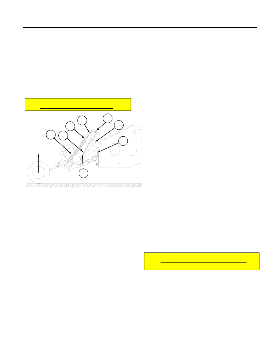
4.3 SUSPENSION ADJUSTMENT
Suspension System Assembly and Parts List
(Illustration May Differ)
1. Lifter Adjustment Bolt (w/rubber stoppers)
2. Spring Bolt
3. Spring Bolt Locking Nut
4. Lifter Adjustment Bolt Locking Nut
5. Spring
6. Lifter Bracket
7. Mounting Bracket Plate
8. Channel Upright
a) Adjust tooth/wheel height. See previous
page.
b) Lower header until wheels just touch the
ground. [Rear roller approximately 20
inches (508 mm) above the ground.]
c) Tighten the spring bolt (2) evenly on both
sides until the wheels begin to lift off the
ground. Turn the spring bolt clockwise to
lift the wheels and counter clockwise to
lower the wheels.
NOTE: The friction in the gas shock
absorbers must be compensated for by lifting
the wheels during tightening and allowing
them to fall to their normal resting position.
The height of the wheels should be checked in
this manner after every 1/2 inch (12mm) of
spring adjustment.
d) Tighten the spring bolt-locking nut (3)
against the spring casting to prevent
loosening.
e) Raise header so wheels are approximately 6
inches (150 mm) off the ground.
f) Lower storage brace into engaged (float
lockout) position and insert clevis pin (see
Section 3.4). If pin does not go in, adjust
lifter adjustment bolt (1) so clevis pin can be
easily installed and removed.
g) Jam the lifter adjustment bolt-locking nut (4)
against the lifter bracket (6).
Note: If ground speed is above 7 mph
(11 km/h) it may be necessary to back off the
float to prevent the header from bouncing
excessively.
Note: During field operation, the rear roller
shaft should be at 14 inches (350 mm) above
the ground.
4.4 SPRINGWIRE/FIBREGLASS
ROD
ADJUSTMENT
The spring wires and the fiberglass rods must be
set properly for different crop and conditions.
a) Remove the clevis and hitch pins and adjust
the spring wire tube so that the spring wires
protrude up through the fiberglass rods as
illustrated. This will protect the fiberglass
rods from becoming damaged by the spring
wire edges.
1
2
4
3
5
6
7
8
Wheels start
to lift off
ground