Maintenance – Multiquip WRS5200DFPU (KUBOTA WG972-GL-E3 DUAL FUEL) User Manual
Page 59
wrs5200dfpu hYdrauLIC roLLer sCreed • operatIon manuaL — rev. #0 (08/18/14) — page 59
maintenance
hYdrauLIC oIL sYstem
The hydraulic system consists of a hydraulic pump directly
coupled to the engine.
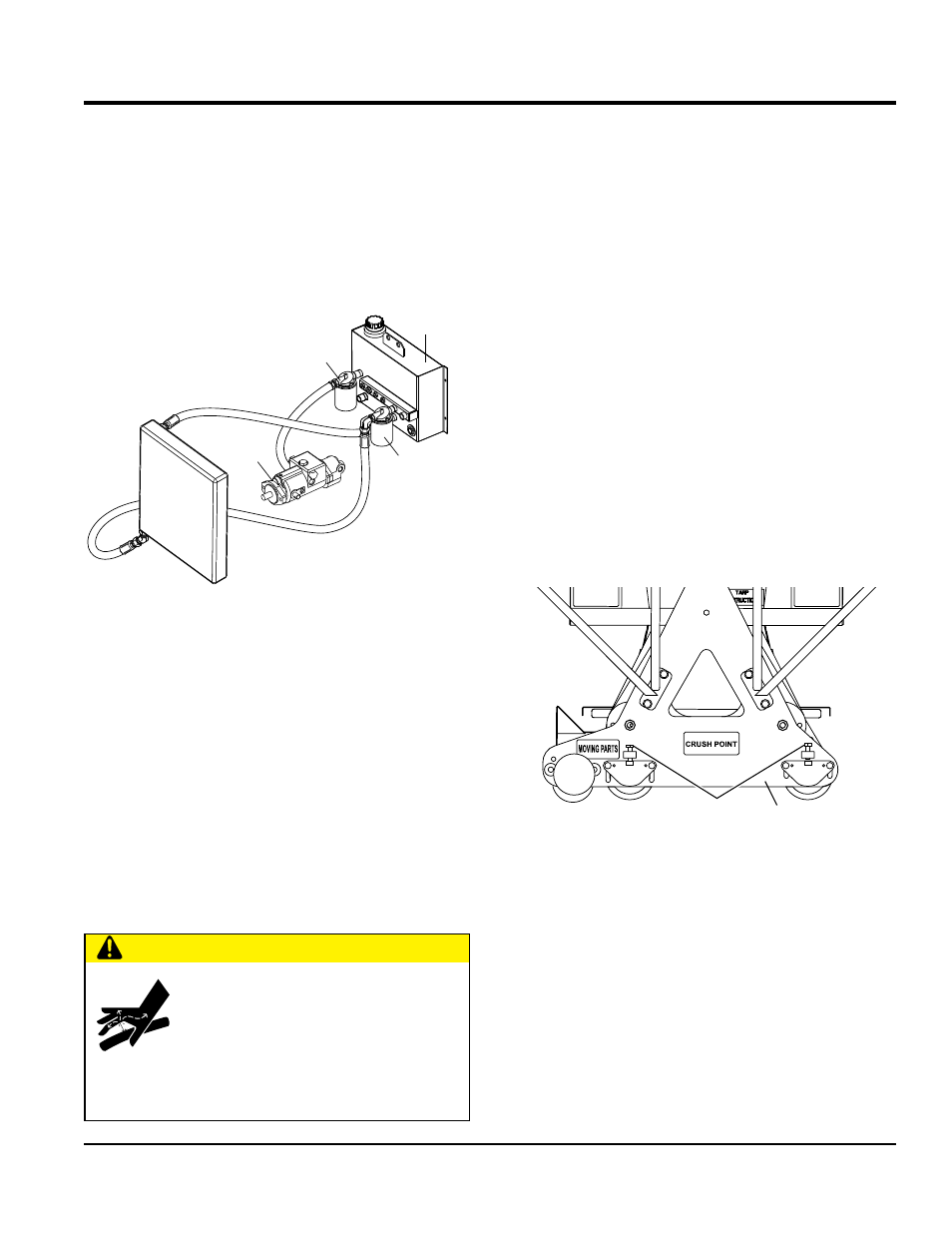
Hydraulic oil is filtered by a screen filter located in the tank
filler neck, a 10 micron inlet filter that connects to the
hydraulic tank and pump, and a 10 micron outlet filter that
connects from the cooler to the hydraulic tank. See
Figure 61.
Figure 61. Hydraulic Filter Locations
It is recommended that ISO 46 type hydraulic oil or equivalent
be used when adding or replacing the hydraulic oil.
do not use muLtI-vIsCosItY oIL. Cleanliness is a
very important part of proper hydraulic system operation.
Hydraulic oil is not only used to transfer power; it also
lubricates and cools the system components. Keeping
the hydraulic system clean can help reduce costly repairs.
The hydraulic oil level sight glass is located on the side of the
hydraulic tank This level should be checked daily. Oil must
be below the top and above the bottom of the sight glass.
do not overfILL! Care should be taken to clean the filler
cap before adding oil to the system. If hydraulic oil has to be
added, the machine should be inspected for leaks.
COOLER
HYDRAULIC
TANK
HYDRAULIC
PUMP
INLET
FILTER
OUTLET
FILTER
CautIon
do not open hydraulic lines or loosen
hydraulic fittings while engine is running!
Hydraulic fluid under pressure can
penetrate the skin, blind, cause burns
or create other potentially dangerous
hazards follow all safety instructions as described
throughout this manual.
Changing Hydraulic Oil and Filters
1. Place the power unit on a clean flat work area and set
the parking brake.
2. Remove the hydraulic oil drain plug and drain
the hydraulic oil. Dispose of the used oil in an
environmentally friendly manner. Replace the drain
plug and tighten.
3. Remove the return filter and install a new filter. Dispose
of the used filter in an environmentally friendly manner.
4. Disconnect the suction hose and remove the fitting from
the tank. Replace the suction filter. Dispose of the used
filter in an environmentally friendly manner. Replace
the fitting and reconnect the suction hose.
adJustIng strIKe tuBe heIght
Strike tube height is adjusted by raising or lowering the
height of the drive tubes. Figure 62 illustrates this. Loosen
the two bolts which hold each drive tube bearing and adjust
the 3/4" bolt to desired height. Tighten the bearing bolts
Figure 62. Strike Tube Adjustment
OUTER
PLATE
DRIVE TUBE
ADJUSTMENT