Ride-on roller screed components – Multiquip WRS5200DFPU (KUBOTA WG972-GL-E3 DUAL FUEL) User Manual
Page 26
page 26 — wrs5200dfpu hYdrauLIC roLLer sCreed • operatIon manuaL — rev. #0 (08/18/14)
riDe-on roller screeD comPonents
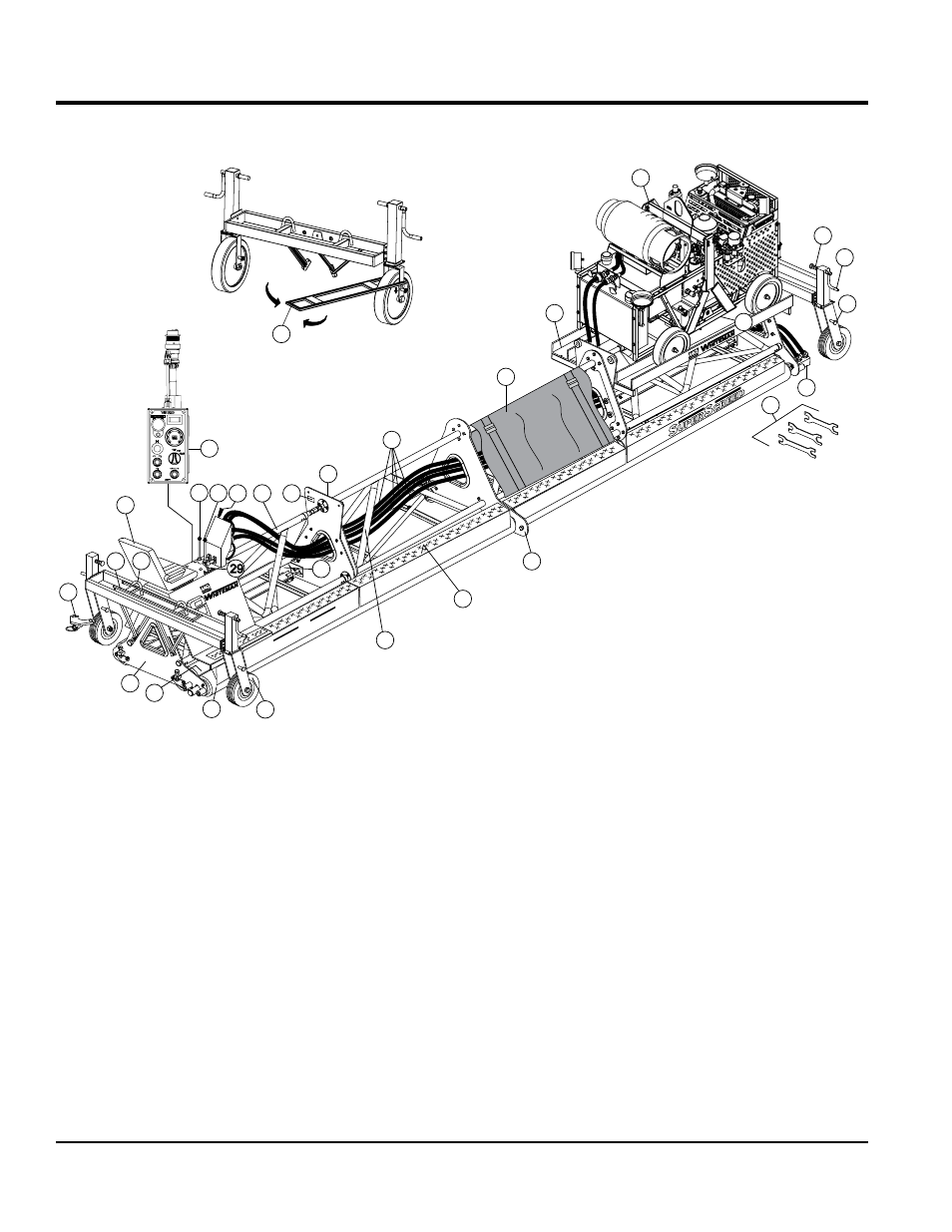
Figure 10. Screed Components
S
S
UPER
CREED
S
S
UPER
CREED
WRS5200
1
4 5
3
6
7
9
10
11
12
13
14
15
16
17
19
21
23
24
25
27
20
28
26
22
25
8
29
18
!
27
2
The definitions below describe the controls and functions
of the Ride-On Power Screed (Figure 10).
1.
Operators Seat — Provides an unobstructed view of
the work area. Seat is adjustable. A safety switch is
located in the seat, getting of the seat will stop drive
tube rotation.
2.
Caster Locks — Used on all four wheels. Once
engaged, they prevent the caster from spinning during
operation
3.
Control Box — Provides vital engine status information
via LEDs. Also contains emergency stop switch, ignition
switch, halogen light switch, engine speed switch, and
hour meter.
4.
drive tube Lever (engine side) — When activated this
3-position lever will cause the
engine side drive tube
to rotate in a clockwise (forward) or counterclockwise
(reverse) direction. The center position is neutral, no
rotation. This drive tube is independent of the operator
side drive tube.
5.
drive tube Lever (operator side) — When activated
this 3-position lever will cause the
operator side
drive tube to rotate in a clockwise (forward) or
counterclockwise (reverse) direction. The center
position is neutral, no rotation. This drive tube is
independent of the engine side drive tube.