5 example project s7-400, 1 hardware configuration, Example project s7-400 – Lenze Drive Server Bus server S7 getting started User Manual
Page 48: Hardware configuration, Busserver s7
Busserver S7
L
109
Busserver S7 DE/EN 1.0
6.5
Example project S7-400
The example project ”LenzeDriveServer” described in this chapter can be found in the sub-directory
\S7 of the DriveServer installation.
6.5.1
Hardware configuration
•
An S7-400 station is used as PLC.
•
CPU 412-2 DP and power supply PS 407 10A are configured in a RACK 400.
•
A PROFIBUS-DP sub-network with master system No. 1 and a baud rate of 1.5 Mbit/s is
available.
•
A Lenze fieldbus module of type 2131 is used as DP slave. This fieldbus module can be used for
8200 and 9300 drive controllers.
–
PROFIBUS address: 9 (hexadecimal)
–
Start address of parameter channel: 1000
–
Start address of process data channel: 1008
–
Consistent communication with 8-byte parameter data and 2 process data words
(Configuration ”PAR(8ByteKons.)+PZD(2Worte)”)
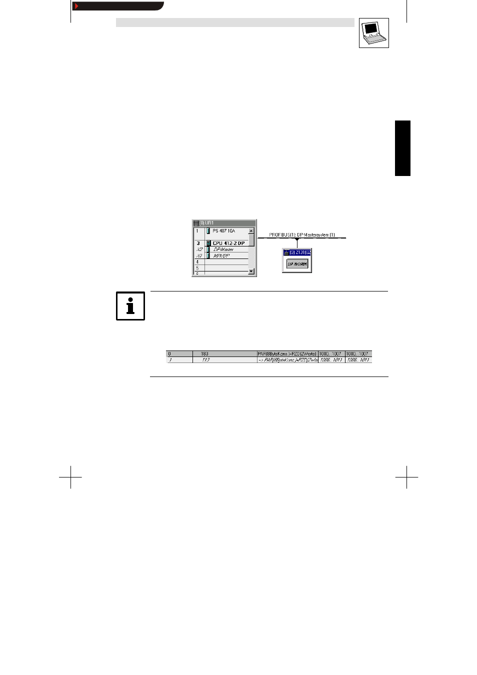
The following figure shows the hardware configuration in the Hardware Manager:
Tip!
The slot table in the Hardware Manager lists the settings of the parameter channel (slot 0) and the
process data channel (slot 1).
The data provided in the columns
I-address and O-address are required to call the function FC92 in
the PLC program:
Slot
I-address O-address
Show/Hide Bookmarks