Device control – Lenze 931K User Manual
Page 60
Device control
State diagram
Status word 1
l
60
KHB 13.0004−EN 2.1
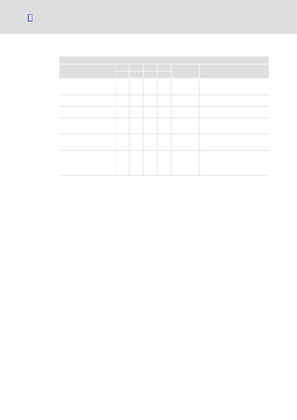
Commands and state transitions of the controller
Control word 1
Command
Bit 3
Bit 2
Bit 1
Bit 0 State
transitions
Description
0008
h
0004
h
0002
h
0001
h
OFF
×
1
1
0
1, 5, 11
The controller is inhibited
(DIN9 = LOW). The motor is braked
to standstill in a controlled manner.
ON
×
1
1
1
2
The controller is enabled
(DIN9 = HIGH).
Coast stop
Ч
Ч
0
Ч
6, 7, 8
The power stage is deactivated. The
drive coasts.
Quick stop
Ч
0
1
Ч
9, 10, 12
The controller is inhibited
(DIN9 = LOW). The motor is braked
to standstill in a controlled manner.
Disable operation
0
1
1
1
4
The controller is inhibited
(DIN9 = LOW). The motor is braked
to standstill in a controlled manner.
Enable operation
1
1
1
1
3
The controller is enabled
(DIN9 = HIGH), the power stage is
activated. The drive is controlled
according to the selected operating
mode.
×
Bit state is not relevant