2 assignment of the interfaces, 1 931e servo inverter, 2 931k servo inverter – Lenze 931K User Manual
Page 14: Assignment of the interfaces, 931e servo inverter, 931k servo inverter, Electrical installation
Electrical installation
Assignment of the interfaces
931E servo inverter
l
14
KHB 13.0004−EN 2.1
4.2
Assignment of the interfaces
4.2.1
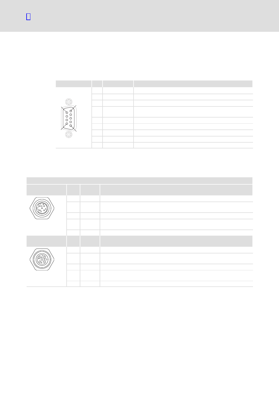
931E servo inverter
The controller is connected to the PROFIBUS via the 9−pin Sub−D socket X4.1/X4.2.
View
Pin
Designation
Explanation
1
6
5
9
1
−
−
2
−
−
3
RxD/TxD−P
Data line B (received/transmitted data plus)
4
RTS
Request to send
(received/transmitted data, no differential signal)
5
M5V2
Data reference potential (ground to 5V)
6
P5V2
5 V DC / 30 mA (bus termination)
7
−
−
8
RxD/TxD−N
Data line A (received/transmitted data minus)
9
−
−
4.2.2
931K servo inverter
The controller is connected to the PROFIBUS via the M12 connector X4.1/X4.2.
X4.1 / X4.2 PROFIBUS
Input contact pattern Pin
no.
Signal
Specification
1
n. c.
Not assigned
2
RxD/TxD−
N
Receive / Transmit data −N (A line)
3
DGND
Data Ground (reference potential to VP)
4
RxD/TxD−
P
Receive / Transmit data −plus (B line)
5
Shield
Shield
Output contact
pattern
Pin
no.
Signal
Specification
1
VP
Power supply plus (5V)
2
RxD/TxD−
N
Receive / Transmit data −N (A line)
3
DGND
Data Ground (reference potential to VP)
4
RxD/TxD−
P
Receive / Transmit data −plus (B line)
5
Shield
Shield