4 state diagram, State diagram, Device control – Lenze 931K User Manual
Page 59
Device control
State diagram
Status word 1
l
59
KHB 13.0004−EN 2.1
8.4
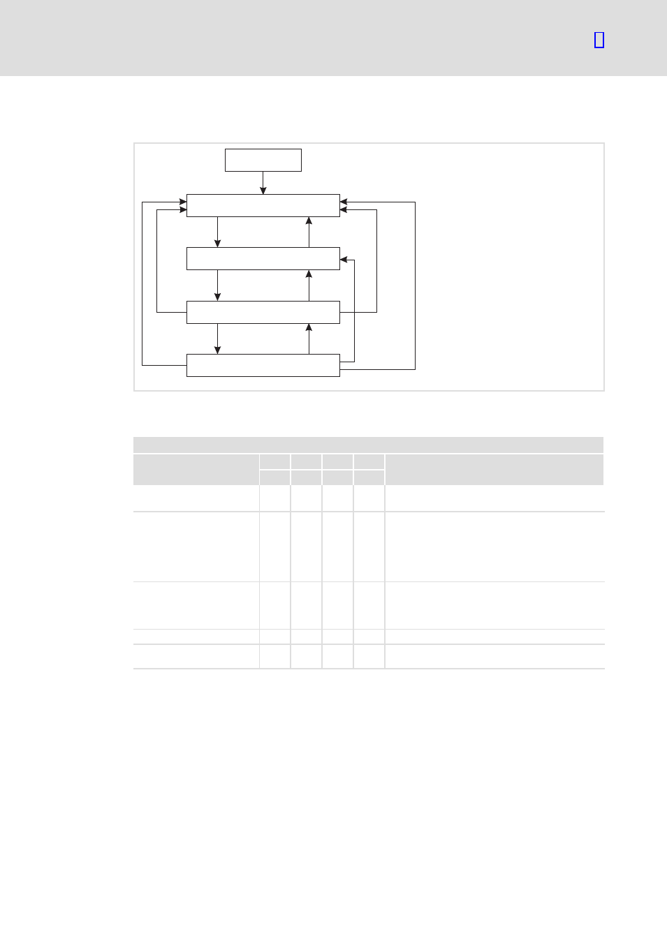
State diagram
Power on
(1)
(2)
(8)
(7)
(9)
(3)
(6) (12)
(5)
(10)
(11)
(4)
S1: SWITCHING_ON_INHIBITED
S2: READY_FOR_SWITCH_ON
S3: SWITCHED_ON
S4:OPERATION
931e_027
Fig. 10
Simplified state diagram
Controller states
Status word 1
State
Bit 6
Bit 2
Bit 1
Bit 0 Description
0040
h
0004
h
0002
h
0001
h
Power on
Switch−on and initialisation of the controller.
Communication via PROFIBUS is not yet possible.
SWITCHING_ON_INHIBITED
1
0
0
0
The initialisation is completed.
The power stage is deactivated, the motor
produces zero torque.
Communication via PROFIBUS is possible.
The controller changes to this state when an error
message occurs.
READY_FOR_SWITCH_ON
0
0
0
1
Waiting for the controller to be enabled.
The controller can be enabled via DIN9 = HIGH or
via the controller enable logic "DIN9 and
PROFIBUS".
SWITCHED_ON
0
0
1
1
The controller is enabled (DIN9 = HIGH).
OPERATION
0
1
1
1
The controller is operating. The drive is controlled
according to the selected operating mode.