4 electrical installation, 1 wiring, Electrical installation – Lenze 931K User Manual
Page 11: Wiring, 4electrical installation
Electrical installation
Wiring
4
l
11
KHB 13.0004−EN 2.1
4
Electrical installation
4.1
Wiring
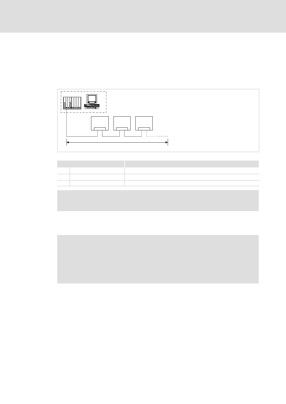
Basic wiring of the PROFIBUS
£ 1200 m
931x
931x
931x
X4.1/X4.2
X4.1/X4.2
X4.1/X4.2
0
1
1
1
931e_037
Fig. 1
Basic wiring
Element
Note
0
Control system
E.g. PC or PLC with PROFIBUS−DP master interface module
1
Bus cable
Adapt baud rate to bus cable length
931X PROFIBUS slave
Appropriate standard device
)
Note!
When using a repeater, up to 125 stations can communicate via PROFIBUS.
EMC−compliant wiring
For wiring according to EMC requirements, please observe the following points:
)
Note!
ƒ
Separate control cables from motor cables.
ƒ
Connect control/data cable shields correctly:
– On both sides for cables with digital signals.
ƒ
Observe the information on wiring according to EMC guidelines given in the
documentation for the standard device.
Wiring procedure
1. Do not change the bus topology, i.e. do not use stubs.
2. Observe wiring notes given in the documentation for the control system.
3. Only use cables that comply with the listed specifications.
4. Activate bus terminating resistors at the first and last physical station.
When using sub plugs Lenze recommends to use sub−D plugs with internal series
inductance (110 nH).