Electrical installation – Lenze HMI for visualisation / with control technology User Manual
Page 31
Electrical installation
Wiring
EL 1xx CAN/PLC/MPI
l
31
LDCDS−EL100 EN 9.0
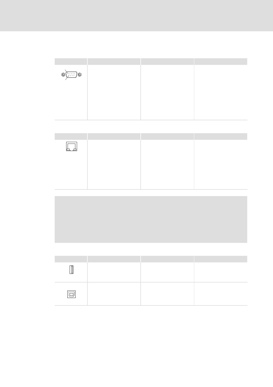
Serial interface
Description
Connection type
Cable type
6
1
RS232 connection
Pin 1: DCD
Pin 2: RxD
Pin 3: TxD
Pin 4: DTR
Pin 5: GND
Pin 6: DSR
Pin 7: RTS
Pin 8: CTS
Pin 9: RI
9−pin Sub−D
plug
Control cable, shielded, with
9−pin Sub−D socket
IPC001
Ethernet interface
Description
Connection type
Cable type
Ethernet connection
10/100 Mbps
Green LED (SPEED):
on = 100 MBPS
off = 10 Mbps
Yellow LED (LINK/ACTIVITY):
on or blinking = LINK
/ACTIVITY
off = no LINK
RJ45 socket
Network cable CAT5 S/UTP or
CAT5e S/FTP (recommended),
cable length: max. 100 m
IPC001
)
Note!
If the RJ45 plug connection is exposed to oscillating or vibrating stress:
ƒ
Use a strain relief in the immediate vicinity of the RJ45 socket.
ƒ
Select the contact surface on which the device is mounted as fixing point of
the strain relief.
ƒ
Comply with the related minimum bending radius of the cable used.
USB interface
Description
Connection type
Cable type
USB 2.0 host connection
Max. load: 5 V/500 mA
USB−A socket
USB cable with USB−A plug
IPC001
USB
USB device connection
USB−B socket
USB cable with USB−B plug
DVI/USB−010