4system description – Lenze Controller-based Automation User Manual
Page 44
4
System description
4.3
Network topologies
44
Lenze · Controller-based Automation - Visualisation · System Manual · DMS 1.5 EN · 04/2014 · TD17
_ _ _ _ _ _ _ _ _ _ _ _ _ _ _ _ _ _ _ _ _ _ _ _ _ _ _ _ _ _ _ _ _ _ _ _ _ _ _ _ _ _ _ _ _ _ _ _ _ _ _ _ _ _ _ _ _ _ _ _ _ _ _ _
Functions
• Access to Siemens S7-300/400 control systems via PROFIBUS (MPI)
• Access to VIPA control systems via PROFINET (RFC1006)
• Visualisation variables can be imported from STEP7®
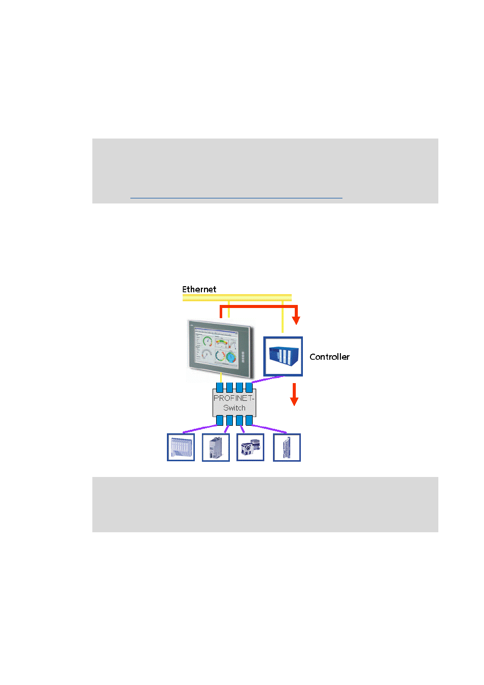
From the view of wiring, a PROFINET network is not a bus in the true sense, but a "switched"
Ethernet with point-to-point connections.
• This structure is described below. The real time data transfer runs via the connections printed in
violet.
• The connections printed in yellow are purely used for Ethernet data transfer. Data are also
transferred via PROFINET without real time interferences.
Note!
The data of the PROFINET field devices connected cannot be accessed directly! As an
alternative, the variables of the field devices should be accessed via the control system.
Access to the control system and the field devices connected
For more information regarding the use of PROFINET®, please see the following sets of
documentation:
• "Controller-based Automation" system manual
• "Controller-based Automation - PROFINET®" communication manual