4system description – Lenze Controller-based Automation User Manual
Page 38
4
System description
4.3
Network topologies
38
Lenze · Controller-based Automation - Visualisation · System Manual · DMS 1.5 EN · 04/2014 · TD17
_ _ _ _ _ _ _ _ _ _ _ _ _ _ _ _ _ _ _ _ _ _ _ _ _ _ _ _ _ _ _ _ _ _ _ _ _ _ _ _ _ _ _ _ _ _ _ _ _ _ _ _ _ _ _ _ _ _ _ _ _ _ _ _
Functions
• Direct access to field devices via CANopen.
Access to the control system and the field devices connected
• Control system access via CAN if the control systems have an SDO object directory.
• Control system access via Ethernet if an OPC server is available.
• SDO and PDO access (only with direct drivers).
• Visualisation variables can be imported from EDS/DCF/GDC files.
Runtime software available for the corresponding device series
For more information regarding the use of CANopen®, please see the following sets of
documentation:
• "Controller-based Automation" system manual
• "Controller-based Automation - CANopen®" communication manual
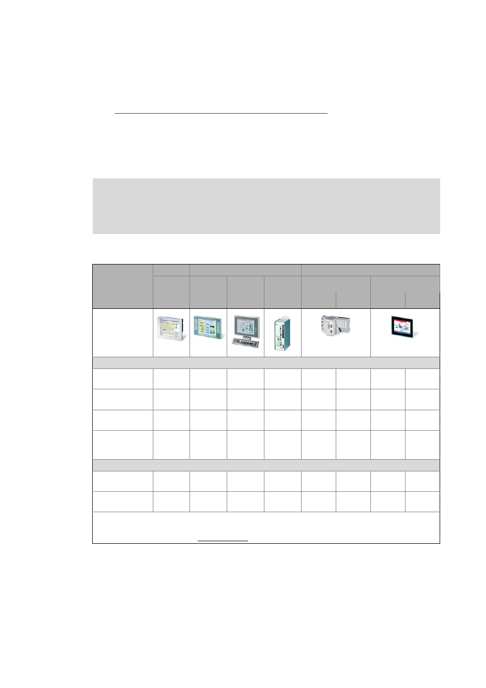
Hardware
HMI
Industrial PCs
Controller
Embedded
Line
Command
Station
Control
cabinet PC
Cabinet Controller
Panel Controller
Device series
EL 100
EL 100 PLC
EL 1800 -
9800
CS 5800 -
9800
CPC 2800
3231 C
3241 C
p300
p500
Example illustration
"Visu" runtime software
»VisiWinNET®«
Compact CE
1)
1)
»VisiWinNET®«
Compact XP
-
-
1)
-
-
»VisiWinNET®«
Standard XP
-
-
1)
-
-
»VisiWinNET®«
Standard
Client/server XP
-
-
1)
-
-
Communication
CAN interface
(on board)
-
-
-
-
-
2)
-
MC-CAN2
(optional)
-
-
:
Function available
-:
Function not available
1) For 3231 C/3241 C, only with external monitor panel/display at DVI interface.
2) Controllers p300 only support the CAN master functionality.