4system description – Lenze Controller-based Automation User Manual
Page 41
Lenze · Controller-based Automation - Visualisation · System Manual · DMS 1.5 EN · 04/2014 · TD17
41
4
System description
4.3
Network topologies
_ _ _ _ _ _ _ _ _ _ _ _ _ _ _ _ _ _ _ _ _ _ _ _ _ _ _ _ _ _ _ _ _ _ _ _ _ _ _ _ _ _ _ _ _ _ _ _ _ _ _ _ _ _ _ _ _ _ _ _ _ _ _ _
Runtime software available for the corresponding device series
Note!
The data of the connected PROFIBUS slaves cannot be directly accessed!
As an alternative, the control system can access variables of the field devices. The control
system automatically reads in the variables and provides them to the visualisation in a
transfer area.
Access to the control system and the field devices connected
For more information regarding the use of PROFIBUS®, please see the following sets of
documentation:
• "Controller-based Automation" system manual
• "Controller-based Automation - PROFIBUS®" communication manual
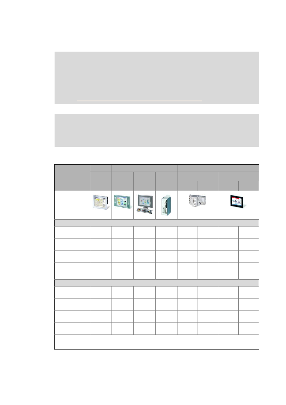
Hardware
HMI
Industrial PCs
Controller
Embedded
Line
Command
Station
Control
cabinet PC
Cabinet Controller
Panel Controller
Device series
EL 100
EL 100 PLC
EL 1800 -
9800
CS 5800 -
9800
CPC 2800
3231 C
3241 C
p300
p500
Example illustration
"Visu" runtime software
»VisiWinNET®«
Compact CE
1)
1)
»VisiWinNET®«
Compact XP
-
-
1)
-
-
»VisiWinNET®«
Standard XP
-
-
1)
-
-
»VisiWinNET®«
Standard
Client/server XP
-
-
1)
-
-
Communication
MPI
(on board)
-
-
-
-
-
-
MC-MPI
(optional)
-
-
MC-PBM, master
(optional)
-
-
MC-PBS, slave
(optional)
-
-
:
Function available
-:
Function not available
1) For 3231 C/3241 C, only with external monitor panel/display at DVI interface.