4 canopen, Canopen, 4system description – Lenze Controller-based Automation User Manual
Page 37
Lenze · Controller-based Automation - Visualisation · System Manual · DMS 1.5 EN · 04/2014 · TD17
37
4
System description
4.3
Network topologies
_ _ _ _ _ _ _ _ _ _ _ _ _ _ _ _ _ _ _ _ _ _ _ _ _ _ _ _ _ _ _ _ _ _ _ _ _ _ _ _ _ _ _ _ _ _ _ _ _ _ _ _ _ _ _ _ _ _ _ _ _ _ _ _
4.3.4
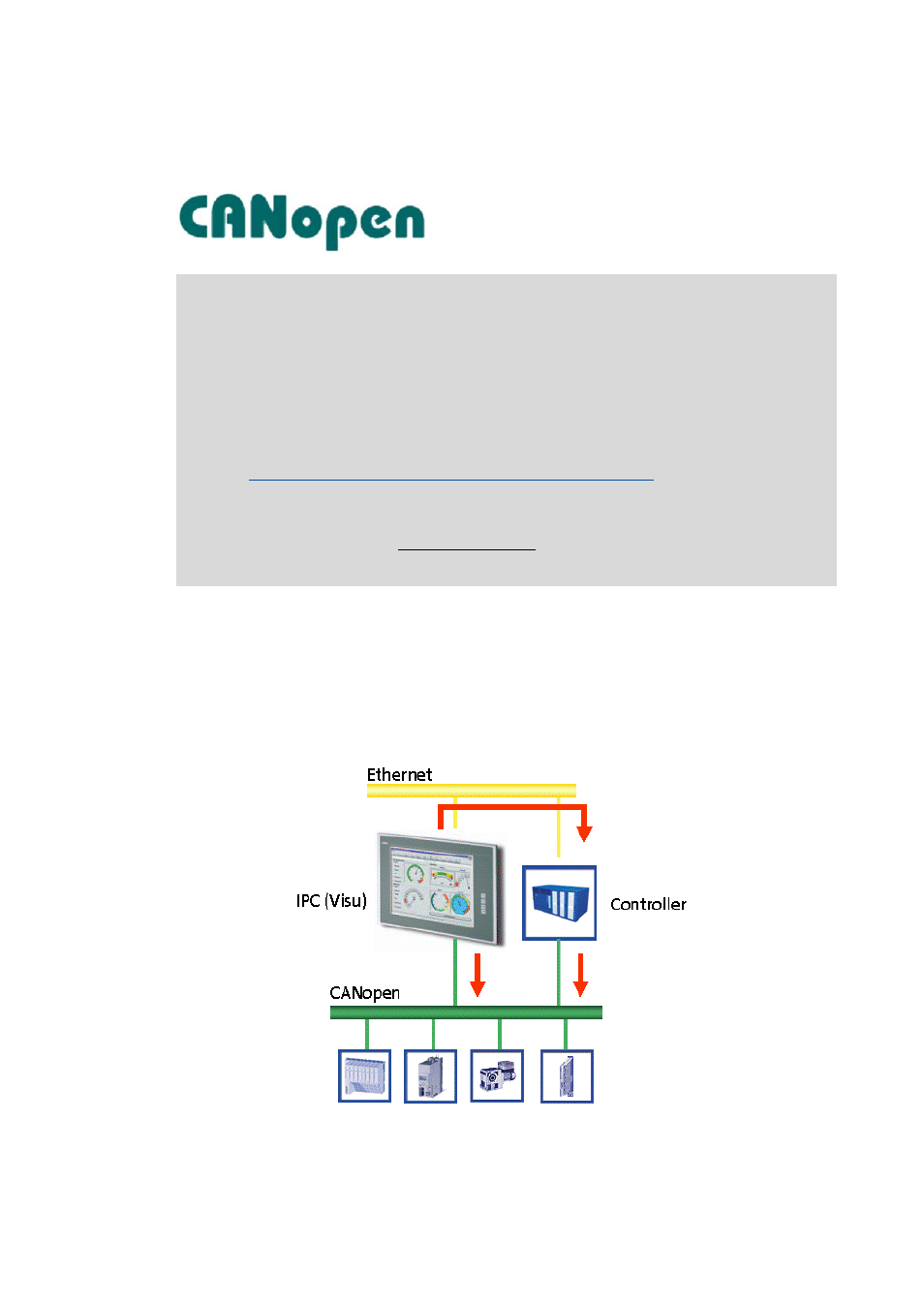
CANopen®
Visualisation applications with CANopen are available for the following Lenze devices:
• HMI series EL 100
• Industrial PCs: EL 1800-9800, CS 5800-9800 and CPC 2800
The Industrial PCs use an OPC server for communication.
• Cabinet Controller 3231 C/3241 C (with an external monitor panel/display)
• Panel Controller p300/p500
Under Windows® CE, a direct driver is provided for communication.
Note!
• Due to the access mechanisms of the CAN bus, the real-time capability of the bus may
be influenced by the visualisation if visualisation and control system communicate
independently of each other with the field devices via CAN. Therefore, this
constellation is only with restrictions suitable for the use in Motion systems.
This restriction does not apply to the Lenze Logic & Motion control system!
• As an alternative, it is recommended to access the variables of the field devices via
Ethernet and control system IPC.
Access to the control system and the field devices connected
Controller p300 ...
• are equipped with an integrated CAN communication interface (on board);
• only support the CAN master functionality.
The optional MC-CAN2 communication card is not supported by controllers p300.