4 replacing the secondary fuses, Replacing the secondary fuses, Troubleshooting – Leica Biosystems ST5020 User Manual
Page 80
80
Instructions for Use, V1.9, RevD - 12/2012
7.4 Replacing the secondary fuses
Four fuse holders, marked F1
through F4, are located at the
rear panel of the instrument,
below the power supply
sockets.
Check the malfunction table
on
page 78
to find out, which
fuse needs to be replaced.
Example:
Touch screen failure:
--> Exchange fuse F1.
Prior to exchanging a fuse, always switch the instrument off and unplug the mains cord.
Defective fuses may be replaced only with the replacement fuses supplied together with
the instrument.
Important!
Follow the instructions below to make sure you select the correct replacement fuse for
each fuse holder.
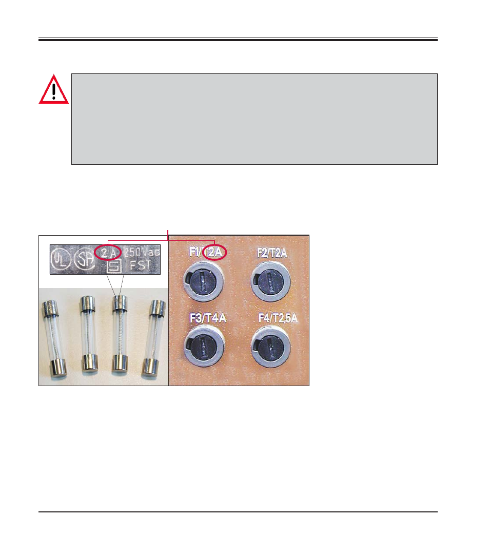
Fig. 72
Selecting the correct replacement fuse
The fuse value is shown on the metal caps of
the replacement fuses - the imprint looking
more or less as indicated above (may vary
slightly depending on the fuse type).
Amperage (A) is the parameter that is important
for allocating fuses correctly to the correspond-
ing fuse holder (in the example above: F1/T2A )
To replace the fuse in fuse holder F1, select the
replacement fuse marked ‘2A‘ (see
Fig. 69
).
Only the fuse marked ’2A‘ can be inserted into
fuse holder F1. The same applies for the remain-
ing fuse holders F2 - F4, i.e. always make sure
the amp rating on the fuse corresponds to the
amp rating indicated above the fuse holder.
The amp value (here: 2A) printed on the fuse and the amp value next to
the fuse holder on the rear panel of the instrument MUST be identical!
7.
Troubleshooting