Area counter/speedometer mode, Warnings and alarms, Area counter/speedometer mode -17 – Kinze 3000 Rigid Frame Planter Rev. 6/14 User Manual
Page 87: Warnings and alarms -17
TM
Model 3000
M0188-01
Rev. 6/11
6-17
KPM II Monitor Operation
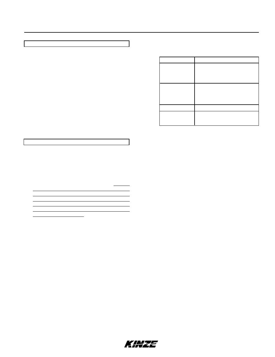
The four possible data communication bus errors
are:
LCD Display
Error Condition
SYS HI
Data communication lead
(green) shorted to power
lead (white).
SYS LO
Data communication lead
(green) shorted to ground
lead (black).
SYS EC
Internal error detected.
COP
Power cycled ON/OFF
too quickly.
2. Under Flow Alarms - If seed rate for one
or more rows is less than 55% of calculated
average, corresponding 60% segment will stay
on, the corresponding row number starts flashing
and the alarm sounds. Pushing the OK key to
acknowledge the warning will turn the alarm off.
The 60% segment of the bar graph remains on
and the row number continues to flash until the
alarm condition is corrected.
NOTE: Alarms present before planting stops are
frozen on screen and LOw or FAIL displays on
the LCD. If under flow is between 0% and 10%,
this warrants a “FAIL” condition. If under flow
is between 10% and 55%, a “LOw” condition is
generated. If multiple rows have an under flow
condition, “FAIL” displays if one or more rows
is between 0% and 10%. This allows the user to
identify and fix problem rows.
NOTE: warning will not trigger unless a minimum
time of continuous planting has passed.
NOTE: If all the rows show a seed rate of zero,
the condition will not generate an alarm. It will
be assumed the planter has stopped. The row
numbers and the bottom 60% segment will remain
on for all selected rows.
3. Multiple Alarms - If more than one alarm
condition occurs at the same time, pushing the
OK key acknowledges all alarms. For example, if
one row on the front and one row on the rear are
alarming, pushing the OK key only acknowledges
one of them. However, if there are two alarms on
the front, both alarms would be acknowledged
with one push of the OK key.
AREA COUNTER/SPEEDOMETER MODE
If the monitor is installed with only a radar distance
sensor (no seed tubes attached), the monitor becomes
a speedometer. If (a) the monitor is connected to a
radar distance sensor, (b) signal cable from back of
console is connected to a sensing switch (Part No.
G1K249 Acre Counter Switch Kit) instead of seed
tubes and (c) implement width in feet (or meters) is
programmed into monitor, monitor functions as an
area counter.
Seed spacing and seed population functions are not
available in this mode. If the monitor is powered down,
the seed tubes connected and the monitor powered
up, the monitor again shows seed population and
seed spacing in inches or centimeters. Row spacing
reverts back to its programmed setting.
wARNINGS AND ALARMS
1. System Alarms - A system alarm is activated
when the monitor detects a faulty sensor or one
of several other communication faults.
The corresponding row number starts flashing
and the audible alarm sounds. All segments on the
corresponding bar graph are turned off. Pushing
the OK key to acknowledge the warning will turn
the alarm off. The row number will continue to
flash until the alarm condition is removed. If the
monitor detects a faulty sensor and there is no
planting activity present, the monitor will scroll
“CHECK CONNECTION”.
If the distance sensor is detected as faulty,
the monitor displays “PICKUP” or “RADAR”,
depending on type of sensor installed, and the
audible alarm sounds. The user can push the
OK key to acknowledge the alarm. When the
distance sensor is faulty, the monitor changes
to a bar graph only mode where rows are still
displayed relative to each other. No area related
information (speed, field area, total area, seed
spacing or seed population) will be accumulated
or displayed.
If a rotation shaft sensor is faulty, “LSHAFT”,
“RSHAFT” or “SHAFTS” displays.
Another type of system alarm occurs when the
monitor detects a data communication bus error.