2 instrument description, Instrument description, Jumo logoscreen fd – JUMO 706585 LOGOSCREEN fd Operating Manual User Manual
Page 17
17
2 Instrument Description
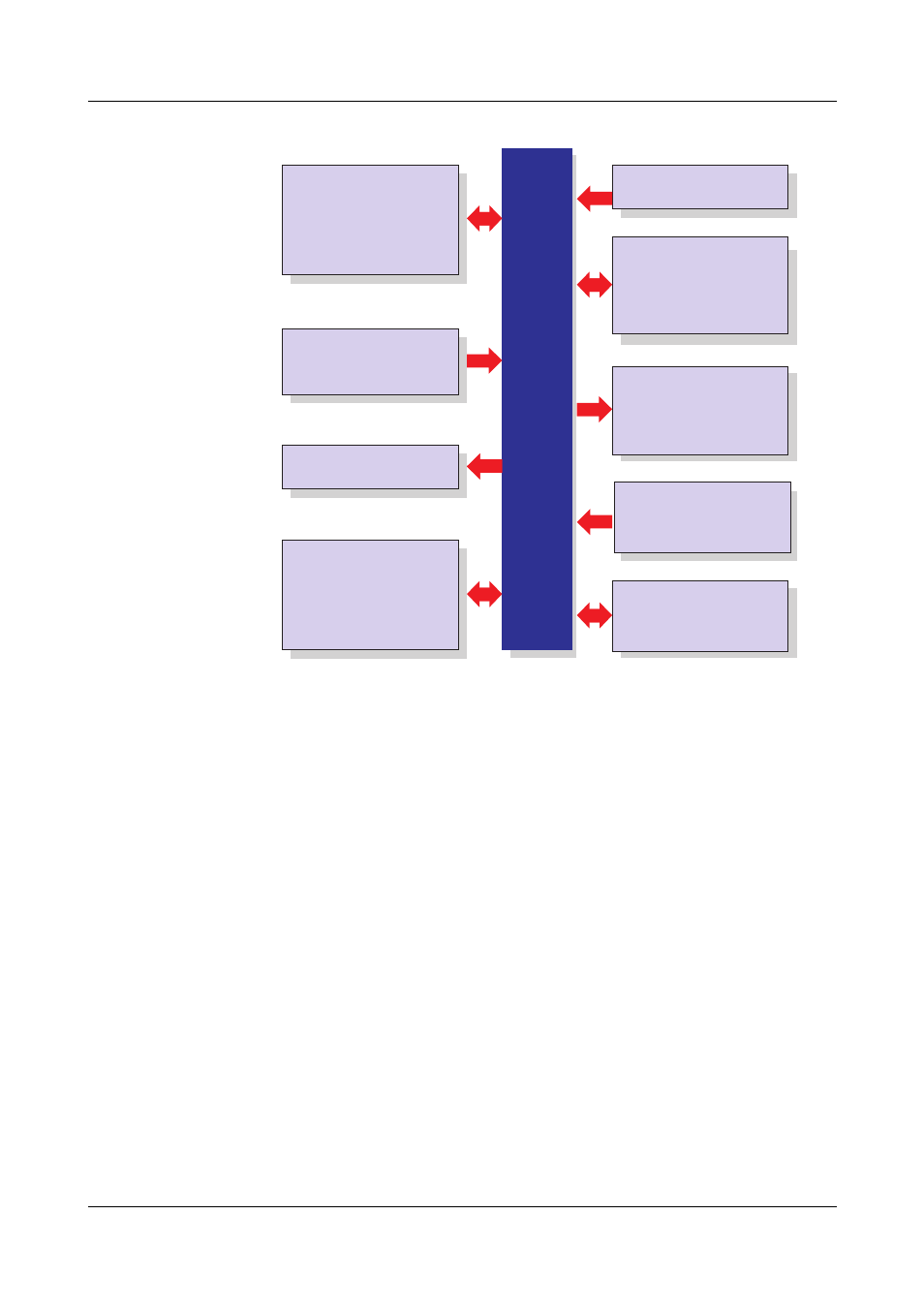
Block diagram
H
The connection diagram is described in the Installation
Instructions B 706585.4(.1). When the paperless recorder is
delivered, a printed version of the installation instructions is
included.
B 706585.4
Installation instructions for recorder
with zinc die-cast panel
B 706585.4.1
Installation instructions for recorder
with stainless steel panel
Setup program,
PCA3000, PCC,
PCS, PCAT
Software
Internal channels
18× math channels
18× logic channels
27× counters/integrators
Inputs/Outputs
0 to 18 analog inputs max.
0 to 24 binary inputs/outputs max.
(maximum of 3 module slots,
can be fitted with 6 analog inputs
or 3 analog inputs
and 8 binary inputs/outputs)
Display/Operation
JUMO LOGOSCREEN fd
Power supply
Display
Operation
5.5" TFT color display,
320 × 240 pixels,
256 colors
rotary knob or touchpad
(left, right, press)
additionally
up to 54 analog inputs and
up to 54 binary inputs
Inputs via interface
1 relay (standard)
additionally
6 relays (option)
Relay outputs
AC 100 to 240 V +10/-15 %,
48 to 63 Hz
AC/DC 20 to 30 V, 48 to 63Hz (ELV)
Interface
as standard
1× RS232/RS485
option:
1× PROFIBUS-DP
1× Ethernet 10/100 Mbits/sec
4× USB interfaces
1× RS232 (barcode reader)
internal memory
256 Mbytes
external memory
CompactFlash card and
USB memory stick
Meas. data memory