Establishing mdc-360c control loop parameters, Stablishing, Mdc-360c – INFICON MDC-360C Thin Film Deposition Controller User Manual
Page 101: Ontrol, Arameters, Table 6-1 default and range for pid parameters -3
MDC-360C DEPOSITION CONTROLLER
Tuning the MDC-360C Control Loop
6-3
gone 48 miles because of some traffic earlier on. Our Integral error is 2 miles. If
we want to get back on schedule we need to speed up a bit. If schedule is very
important to us, we will speed up a lot to get back on schedule fast. If schedule is
not important at all we will maintain our speed. The Integral Time constant
instructs the controller on how much attention to pay to the schedule. If we don’t
care what happened in the past and we want zero rate error right now, we don’t
want any Integral feedback. To accomplish that we set the Integral Time constant
to its maximum value, which tells the controller to ignore any past error unless it
lasts for a very long time.
6.3
ESTABLISHING MDC-360C CONTROL LOOP PARAMETERS
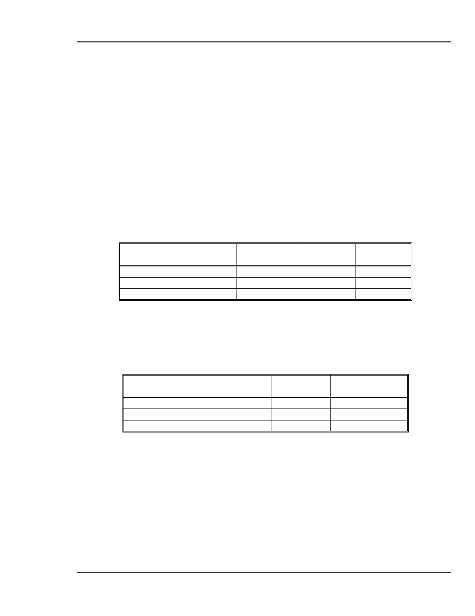
As explained above, the MDC utilizes three control loop parameters referred to as
PID parameters; Proportional gain, Integral Time constant and Derivative Time
constant to provide for optimization of the control loop. The MDC provides
default values for each of these parameters.
Parameter
Minimum
value
Maximum
value
Default
value
Proportional gain
1
9999
1000
Integral time constant, sec.
0
99.9
99.9
Derivative time constant sec.
0
99.9
0.0
Table 6-1 Default and Range for PID Parameters
The following table lists some recommended PID values for different types of
deposition sources. These values represent a good starting point and in some
cases may not need to be further modified.
Parameter
Electron
Beam Gun
Filament Boat
Proportional gain
2000
600
Integral time constant, sec.
99.9
99.9
Derivative time constant sec.
25.0
75.0
Table 6-2 Suggested PID Starting Values for Different Sources
In the MDC-360C, the PID parameters are defined at the material level because
different materials often require different PID settings even though they may be
deposited from the same source. Therefore it is usually necessary to establish the
PID parameters for every each material and deposition source.
The first step in setting the PID parameters for a new material or source is to enter
the recommended starting values listed above. Be sure and choose the PID values
for the type of source you're using. Next, create a dummy process with the first
layer set for the new material. Start and abort the dummy process to load the new
material as the active material. You should now see the material's name in the top
line of any Status Screen. Next, open the shutter and put the MDC-360C in the