Flint & Walling CPJS Shallow Well User Manual
Page 7
7
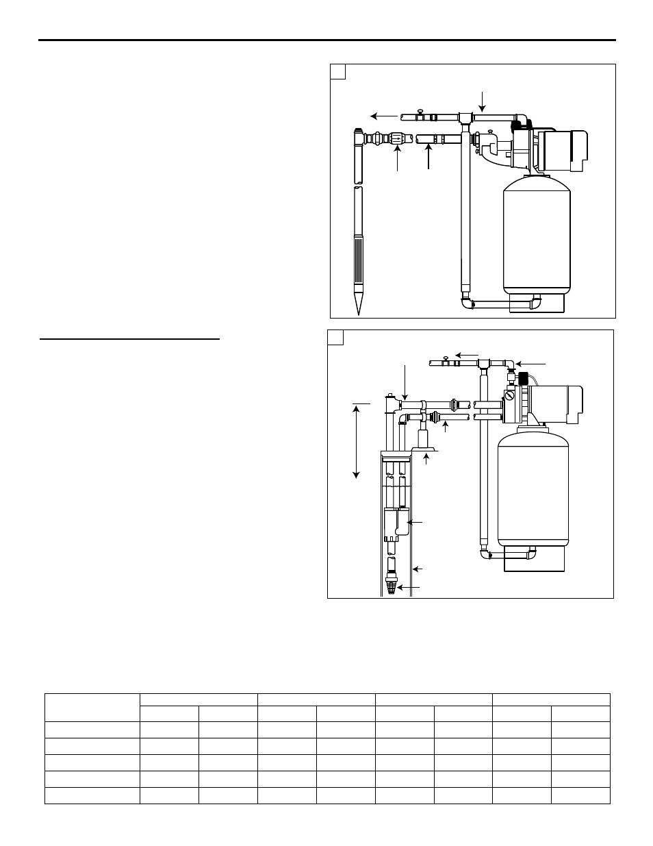
INSTALLING PIPING IN WELL
IL1188
3/4 or 1 in.
Discharge Pipe
1-1/4 in.
Suction
Pipe
Discharge
to Home
Check
Valve
2
RECOMMENDED SUCTION PIPE SIzES FOR SHALLOW WELL PUMP CHART 5
Motor
HP
Vertical Piping Size
Length of Offset from Well
0-20’
20-100’
100-200’
200-400’
1/3
1’
1”
1-1/4”
1-1/2”
2”
1/2
1”
1”
1-1/2”
1-1/2”
2”
3/4
1-1/4”
1-1/4”
1-1/2”
2”
2”
1
1-1/4”
1-1/4”
1-1/2”
2”
2”
1-1/2
1-1/4”
1-1/4”
1-1/2”
2”
2”
When connecting a drive point (Fig. 2) a check valve must
be used in the suction line in place of a foot valve. For easy
priming connect the check valve as close to the well as
possible.
All piping from the well to the pump should slope slightly
upward with no sagging. Support suction pipe between
water source and pump. Unions in the suction line near
the pump and well will aid in servicing. Be sure to leave
enough room so that wrenches can be used easily.
Deep Well (Double Pipe System)
Where water level is greater than 25 feet and inside
diameter of well is four (4) inches or larger (Fig. 1).
1. Attach the foot valve to the ejector using a galvanized
steel or plastic nipple. Add enough 1 in. pressure pipe
and 1-1/4 in suction pipe to submerge ejector 10 to 15’
below pumping water level, making certain foot valve is
at least five (5) feet from bottom of well. If pressure pipe
and suction pipe of the same diameter are used, be sure
to identify them clearly so that they will be connected to
the proper tappings of the pump.
If a known well leak exists, replace nipple with 21 feet
of 1” tail pipe between the ejector and the foot valve.
This will provide a continuous source of water for the
pumping system.
2. Check pipe and foot valve for leaks by filling pipes with
water. A continuous loss of water indicates a leak in the
piping, foot valve or unions, and must be corrected.
3. If no leaks are found, proceed to
WELL TO PUMP
CONNECTION (SUCTION PIPE). For long offset
distances, see Table B for proper pipe size.
4. All piping from the well to the pump should slope slightly
upward with no sagging. Support suction pipe between
water source and pump. Unions in the suction line near
the pump and well will aid in servicing. Be sure to leave
enough room so that wrenches can be used easily.
IL1184
Water
Level
Suction
Lift
3/4 or 1 in.
Discharge
Pipe
Suction
Pipe See
Table B
Discharge
to Home
Pipe
Support
Foot Valve
Pressure
Pipe See
Table B
4 in. ID Well
Ejector
1
PIPE SIzES REqUIRED FOR OFFSET PIPING FOR DEEP WELL EJECTOR INSTALLATION TABLE B
Distance Well to
Pump
1/3 HP
1/2 HP
3/4 HP
1 & 1-1/2 HP
Suc.
Press.
Suc.
Press.
Suc.
Press.
Suc.
Press.
0-25’
1-1/4”
1”
1-1/4”
1”
1-1/4”
1”
1-1/4”
1”
25-50’
1-1/4”
1”
1-1/4”
1-1/4”
1-1/2”
1-1/4”
1-1/2”
1-1/4”
50-75’
1-1/4”
1-1/4”
1-1/4”
1-1/4”
1-1/2”
1-1/2”
1-1/2”
1-1/2”
75-100’
1-1/2”
1-1/4”
1-1/2”
1-1/4”
1-1/2”
1-1/2”
2”
1-1/2”
100-150’
1-1/2”
1-1/4”
1-1/2”
1-1/2”
2”
1-1/2”
2”
2”