Flint & Walling CPJS Shallow Well User Manual
Page 6
6
Tools required
PREPARATION
Pipe wrenches (2)
Wire strippers
Needle-nose pliers
Phillips screwdriver
Wire cutters
Adjustable wrench
Pipe tape
Pipe dope
NOTE: For a successful installation, take time to study your application for the correct pipe size and appropriate fittings.
The illustrations in these instructions will assist you with required and optional fittings. Sch. 40 PVC plastic pipe and
fittings were used in these instructions.
Before beginning installation of product, make sure all parts are present. If any part is missing or damaged, do not
attempt to assemble the product. Contact customer service for replacement parts.
Estimated Installation Time: 2 hours.
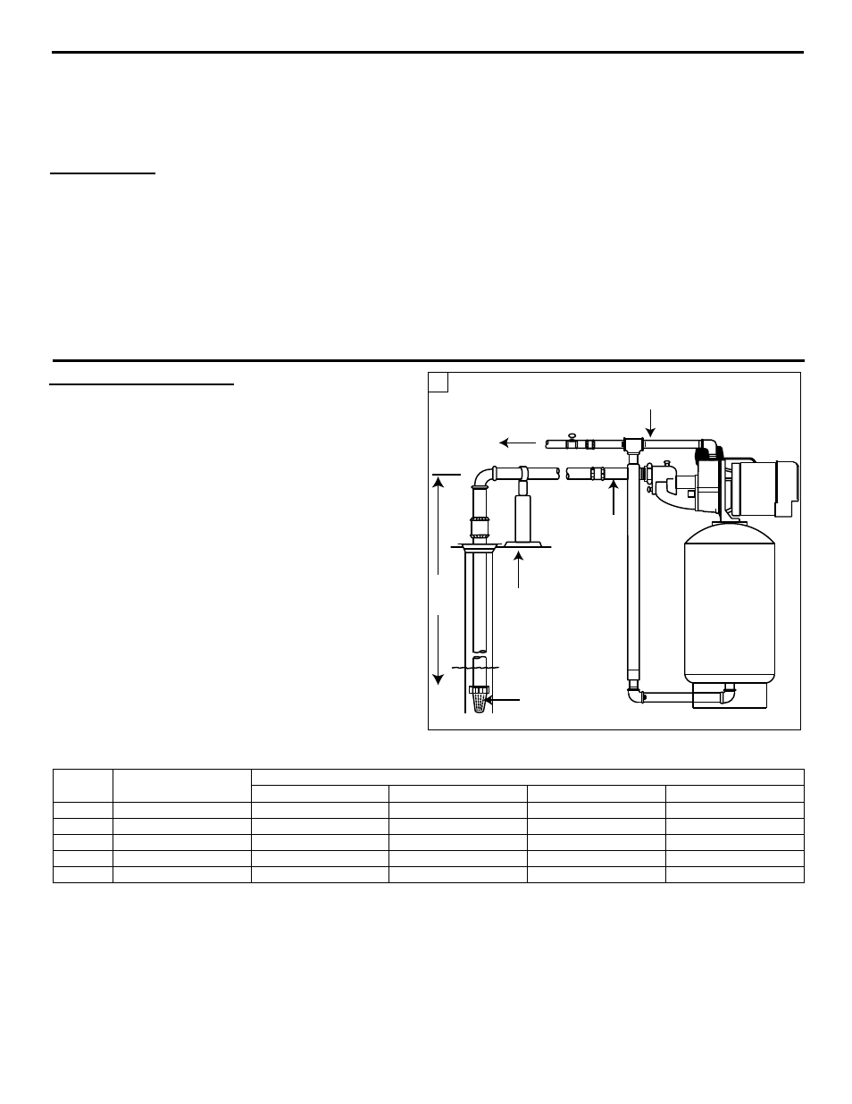
Shallow Well Application
- Where Suction Lift Is Less Than 25 Feet
On single pipe installations (Fig. 1) attach foot valve to the
end of the suction pipe and set in the well, making certain
the valve is below the water level. The foot valve should
at least five (5) feet from the bottom of the well to prevent
sand from being drawn into the system.
IL1187
Water Level
25 ft.
Max
Suction
Lift
3/4 or 1 in.
Discharge Pipe
1-1/4 in.
Suction
Pipe
Discharge
to Home
Pipe
Support
Foot Valve
1
RECOMMENDED SUCTION PIPE SIzES FOR SHALLOW WELL PUMP CHART 5
Motor
HP
Vertical Piping Size
Length of Offset from Well
0-20’
20-100’
100-200’
200-400’
1/3
1’
1”
1-1/4”
1-1/2”
2”
1/2
1”
1”
1-1/2”
1-1/2”
2”
3/4
1-1/4”
1-1/4”
1-1/2”
2”
2”
1
1-1/4”
1-1/4”
1-1/2”
2”
2”
1-1/2
1-1/4”
1-1/4”
1-1/2”
2”
2”
INSTALLING PIPING IN WELL