15 pump electrical connections, 1wiring the pressure switch, Wiring diagram – Flint & Walling CPJS Shallow Well User Manual
Page 15
15
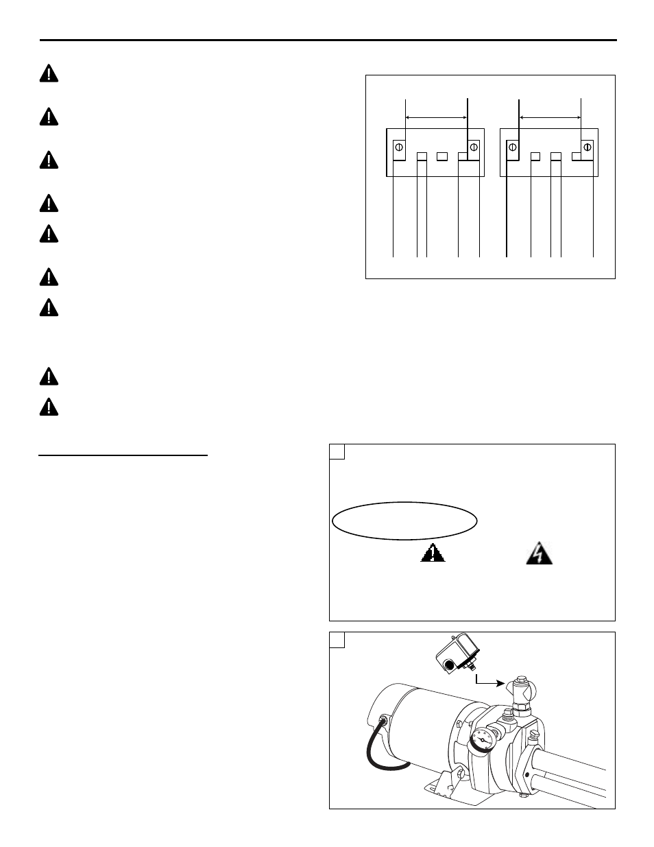
PUMP ELECTRICAL CONNECTIONS
IL1401
2
L1
L2
A
B
L1
L2
A
B
115 Volts
Single Phase
Line
230 Volts
Single Phase
Line
Y
E
L
L
O
W
W
H
I
T
E
G
R
E
Y
R
E
D
T
A
N
Y
E
L
L
O
W
W
H
I
T
E
G
R
E
Y
R
E
D
T
A
N
Check Voltage of Power Source
Before Connecting
DO NOT CONNECT ANY GROUND WIRE
TO THESE LEADS
WIRING DIAGRAM
2. Screw the pressure switch into the 1/4 in. opening on the
side of the flow control and remove the switch cover. (Fig.
2)
CAUTION: All wiring should be performed by a
qualified electrician in accordance with the National
Electric Code and local electric codes.
CAUTION: Connect the pump to a separate electrical
circuit with a dedicated circuit breaker. Refer to the
Wire Size Chart for proper fuse size.
WARNING: Under-size wiring can cause motor failure
and even fire. Use proper wire size specified in the
Wire size chart.
WARNING: Replace damaged or worn wiring cord
immediately.
WARNING: Do not kink power cable and never allow
the cable to come in contact with oil, grease, hot
surfaces, or chemicals.
CAUTION: Protect the power cable from coming in
contact with sharp objects.
CAUTION: Make certain that the power source
matches the pump requirements. This pump has a
dual voltage motor and can run on 115V or 230V. See page
20. 1/2 HP pumps are wired from the factory to run on 115V.
3/4 & 1 HP pumps are wired from the factory to run at 230V.
WARNING: The pump must be properly grounded
using the proper wire cable with ground.
WARNING: Always disconnect pump from electricity
before performing any work on the motor.
S
TAR
®
C
US
LR90197
UL Std. No. 778
ENCLOSURE 3
starwatersystems.com
Pump:
ES05S
Rev:
B
Motor:
98L105
HP:
1/2
PH
1
Hz
60
Volts
115/230
S.F.
1.2
Amps
6.4/3.2
S.F. Amps:
8.6/4.3
RPM
3450
Type
C
Duty:
Cont.
Temp
65C
KVA Code
G
Frame
56L
Ins Class
B
Factory prewired for 115V
Thermally protected automatic
Check voltage of power source
Use copper conductors only
ELECTRICAL HAZARD
Improper installation may result in fi re, explosion, electrical short or injury. Replace all covers
before operating. Ground motor in accordance with local and national electrical codes.
Disconnect power source before touching internal parts. Motors equipped with automatic
protection may restart without warning.
See instruction manual for proper installation procedure.
Se reporter au manuel d’instructions pour suivre la procédure adéquate d’installation.
Consulte el instructive para conocer el procedimiento de instalación correcto.
L1
L2
A
B
L1
L2
A
B
IL0180
YELLOW
115 VOLT
SINGLE PHASE
LINE
230 VOLT
SINGLE PHASE
LINE
WHITE
GRAY
RED
TAN
YELLOW
WHITE
GRAY
RED
TAN
DATE CODE:
0713*
Made in USA
1
Wiring The Pressure Switch
1. CAUTION: Make certain that the power source matches
the pump requirements. This pump has a dual voltage
motor and can be wired by the customer to run on 115V
or 230V. (Fig. 1)
NOTE: To change pump voltage, see wiring diagram on this
page or step-by-step instructions on page 18.