8 repair, 9 accessories, 10 eliminating malfunctions – Festo DGC-8 ... 63-... User Manual
Page 8: 11 technical data
Lubricating the guides of types
G and GF:
• Lubricate the guide rail if it no longer has a layer of grease, but at the latest:
– every 3000 km or every 3 years. Grease type: LUB-KC1 (for DGC-
8-G/GF)
– every 1000 km or every 2 years. Grease type: LUB-E1 (for DGC-...-G/GF-
H1)
• Note that lubrication must be undertaken more often:
– if the environment is dusty and contaminated
– with work strokes of
< 50 mm
– ambient temperatures
> 40°C.
The remaining sizes of types G/GF do not require any maintenance (relubrication
however is permitted).
Lubricating the guide of type
KF:
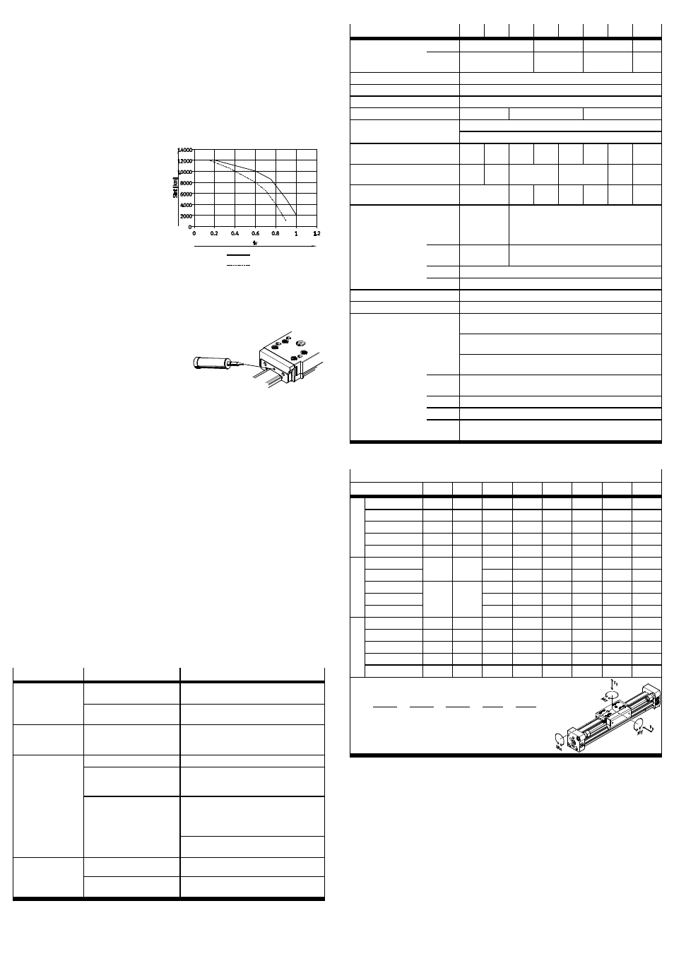
The lubrication intervals S
int
depend on
the load of the guide.
1. Calculate the load comparison factor
f
v
with the aid of the formula for
combined loads (
Technical data)
and determine the lubricating
interval S
int
from Fig. 24.
• Always lubricate the DGC at the
latest every 3 years (every 2 years
for the DGC-...-KF-...-H1).
Fig. 24
DGC
DGC-H1
• Note that lubrication must be undertaken more often:
– if the environment is dusty and contaminated
– with work strokes of
< 50 mm or > 2000 mm
– at speeds of
> 2 m/s
– in ambient temperatures of
> 40°C.
2. Lubricate the roller bearing through
the holes on both sides of the slide.
For this purpose use a grease gun
with a pointed nozzle or alternatively
a disposable syringe with needle.
Fig. 25
Permitted grease types:
DGC-8/12-KF:
LUB-LG0
DGC-18 … 63-KF:
LUB-RN2
DGC-8 … 63-KF-H1:
ELKALUB VP 874 (from Chemie-Technik)
• Push the slide backwards and forwards during lubrication.
Otherwise the grease cavities will not be filled to an equal extent.
Alternatively, Festo offers a service inspection which includes lubrication.
Otherwise the DGC does not require any maintenance.
8
Repair
• Recommendation: Return the product to our repair service for overhaul.
This ensures that special attention will be paid to the necessary fine adjust-
ments and inspections.
• Information on spare parts and aids can be found under:
www.festo.com/spareparts
Replacing cushioning elements:
• Note the section “Accurate adjustment of the stroke” in the chapter “Commis-
sioning”.
9
Accessories
Please select the appropriate accessories from our catalogue
www.festo.com/catalogue/DGC
10
Eliminating malfunctions
Malfunction
Possible cause
Remedy
Uneven movement
of the slide
One-way flow control valve
not fitted correctly
If possible reduce the exhaust
(not the supply air)
Guide rail not greased
Lubricate guide rails in accordance with
chapter “Care and maintenance”
Faults in position
scanning
Ferritic parts in the vicinity
of the proximity sensor
Use parts made of non-magnetic materials
or observe minimum distances
(
5.3. Installing the electric components)
Heavy leakage
Cylinder is distorted
Fasten the cylinder to a flat base.
Seal worn
Replace worn parts:
– Yourself with wearing parts kit
– By returning to Festo for repairs
Sealing band pressed in/
sucked in
When the linear drive is unpressurised,
move the slide twice manually through the
entire stroke (if necessary, push fixed stops
into the end position)
Avoid vacuum in the piston chamber
(e.g. move the unpressurised slide slowly)
Cylinder does not
reach the desired
speed
Air volume not sufficient
– Select tubing with larger diameter
– Switch volume upstream
High friction or
counteracting force
Observe maximum limits
Fig. 26
11
Technical data
DGC-
8
12
18
25
32
40
50
63
Pneumatic
connection
DGC
M5
G
Á
G
¼
G
Å
DGC-N
M5 suitable for
10-32 UNF
Á NPT
¼ NPT
Å
NPT
Mode of operation
Double-acting
Mounting position
Any
Operating medium
Compressed air in accordance with ISO8573-1:2010 [7:-:-]
Operating pressure
[bar]
2.5 … 8
2 … 8
1.5 … 8
Ambient temperature
[°C]
–10 … +60
+5 … +60 (DGC-
8-G)
Theoretical force
at 6 bar
[N]
30
68
153
295
483
754
1178
1870
Speeds (min ... max)
[m/s]
0.15
… 1
0.1
… 1.2
0.05
… 3
0.04
… 3
0.03
… 3
0.02
… 3
Cushioning length
PPV
[mm]
–
16.5
15.5
17.5
29.5
29.8
31.1
Cushioning
P
Flexible
cushioning
rings/pads
at both ends
–
PPV
–
Pneumatic cushioning, adjustable at both
ends
YSR
Shock absorber, hard characteristic curve
YSRW
Shock absorber, progressive characteristic
Max. energy
For diagrams, see catalogue specifications
Note on materials
KF
Free of copper and PTFE
Materials
Scraper, band reverser,
cover:
Polyacetal/polyamide
Piston seal, cushioning seal,
sealing band, cover band:
Polyurethane
Stops:
Steel, corrosion resistant/
coated
G
End cap, cover, slide:
Aluminium, coated/
polyamide
GF
Slide:
Aluminium, anodised
G/GF
Cylinder profile, guide rail:
Aluminium, anodised
KF
Guide rail, slide:
Steel, corrosion resistant/
coated
Fig. 27
Permitted force and torque loading
DGC-
8
12
18
25
32
40
50
63
G
Fymax
[N]
150
300
70
180
250
370
480
650
Fzmax
150
300
340
540
800
1100
1600
2000
Mxmax
[Nm]
0.5
1.3
1.9
4
9
12
20
26
Mymax
2
5
12
20
40
60
150
150
Mzmax
2
5
4
5
12
25
37
48
GF Fymax
[N]
–
–
440
640
900
1380
1500
2300
Fzmax
540
1300
1800
2000
2870
4460
Mxmax
[Nm]
–
–
3.4
8.5
15
28
54
96
Mymax
20
40
70
110
270
450
Mzmax
8.5
20
33
54
103
187
KF Fymax
[N]
300
650
1850
3050
3310
6890
6890
15200
Fzmax
300
650
1850
3050
3310
6890
6890
15200
Mxmax
[Nm]
1.7
3.5
16
36
54
144
144
529
Mymax
4.5
10
51
97
150
380
634
1157
Mzmax
4.5
10
51
97
150
380
634
1157
f
v
=
|Mx|
Mx
max
+
|My|
My
max
+
|Mz|
Mz
max
+
|Fy|
Fy
max
+
|Fz|
Fz
max
≤ 1
Formula for combined loadings:
Fig. 28