Emergency modules, About emergency modules, Connection – ETC Sensor3 CE (ESR3) Rack User Manual
Page 44: A p p e n d i x c, About emergency modules connection
36
Sensor3 CE Rack (ESR3) Installation Manual
A p p e n d i x C
Emergency Modules
About Emergency Modules
Sensor3 CE Emergency modules provide two live outputs, one of which is dimmed or
switched, and one of which is live whenever the breaker is turned on. This allows the
modules to control battery backed lighting which requires a constant and a switched or
dimmed feed.
There are two varieties of Emergency Module - ED15AFE (15A Dimmer), and
ER15AFE(15A Relay). They are painted red for easy identification.
Connection
The constant output from the module is connected to the neutral lugs at the left of the rack.
Therefore, unlike neutral disconnect modules, emergency modules provide a live output at
these lugs, not a neutral connection. There is no neutral disconnect or RCD version of the
emergency modules.
Step 1:
Locate the slot where the Emergency module is to be fitted.
Step 2:
Terminate the outgoing dimmed line to the terminals at the right hand side of the
rack.
Step 3:
Terminate the outgoing constant feed line to the terminals at the left hand side of
the rack.
Step 4:
Terminate the outgoing earth to the earth bar terminals.
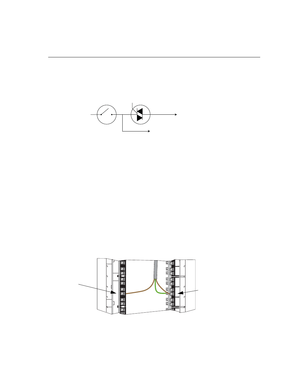
Figure 35: Emergency Module Circuit
Module Circuit Breaker
Dimming or Relay Circuit
Dimmed or Switched Output
Constant Output
Figure 36: Emergency Module Connections
Constant live
line is landed
on the neutral
lugs
Dimmed or
switched line is
landed on live
lugs